how to wire two solar panels together
If you’re standing in your garage with two solar panels and a handful of MC4 connectors, you’ve probably already asked yourself the same question I hear all the time: how to wire two solar panels together without frying your charge controller or lighting a fire. It’s one of those deceptively simple tasks where one wrong connection can cost you weeks of troubleshooting or worse, a fried inverter. The good news?
The decision comes down to just two numbers on your panel’s spec label and one number on your charge controller.
Manufacturer specifications for residential PV modules used in 2026 typical 12V systems show Voc ranging from 18V to 24V per panel, while MPPT charge controllers commonly accept up to 100V or 150V at their input. Understanding that voltage ceiling is the entire key to choosing the right wiring method. Let’s walk through exactly what you need to check before you touch a single wire.
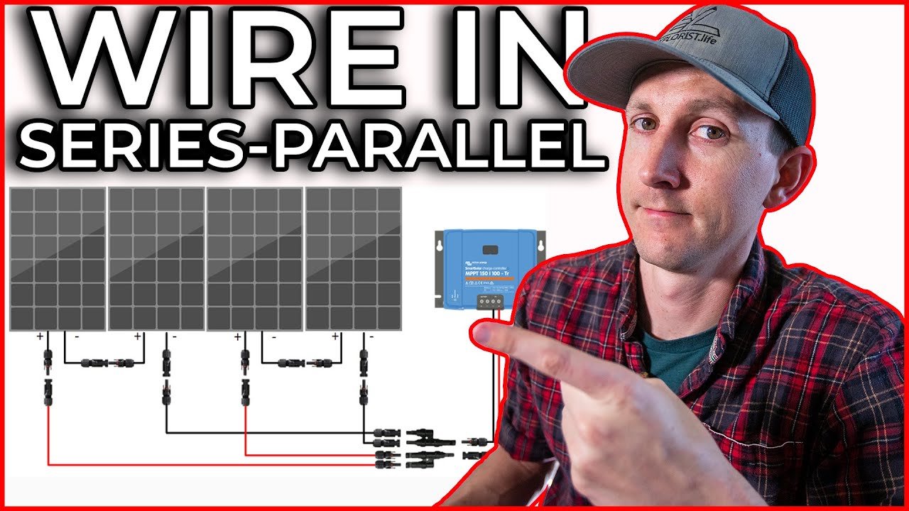
Image source: EXPLORIST life Mobile Marine & Off-Grid Electrical (YouTube thumbnail, fair use)
Why Getting the Wiring Right Actually Matters (And When It Can Go Wrong)
Wiring two solar panels together isn’t just about matching colours. Get it wrong and you could overload your charge controller, create a fire risk from undersized wire, or end up with half the charging power you expected. In our research, the most common DIY mistake is assuming you can just connect both panels directly to the controller without checking the total voltage, especially on cold mornings when Voc can spike 10, 15% above the label rating.
The stakes are higher than many people realise. A 200W array wired in series on a controller rated for 100V max might seem fine on a warm afternoon, but on a frosty morning that same array could push 110V or more. That’s a one-way ticket to blowing the input stage of your controller.
Similarly, parallel wiring without proper fusing can turn a panel fault into a sustained arc that melts connectors. So the wiring choice isn’t academic, it’s a safety and performance decision.
The right setup also determines how much power you actually harvest. A mismatched series connection with different wattage panels can drop total output to the level of the weakest panel. A parallel connection with a PWM controller running on long cable runs can lose 20% or more to voltage drop.
Knowing the rules upfront saves you both time and money.
Quick Answer: Series vs. Parallel vs. Series-Parallel in One Sentence
Wire in series to double voltage. Wire in parallel to double current. Use series-parallel only when you have four or more panels and need to stay within a charge controller’s limits.
That’s the essence. The rest is about matching those numbers to your hardware. For two panels specifically, you have exactly two real choices, series or parallel.
Series is almost always better for MPPT controllers because higher voltage means lower current, thinner wire, and less loss. Parallel is the fallback for PWM controllers or when your panels have different specs and you can’t pair them in series.
Here’s the decision rule in one table:
| Condition | Recommended Wiring |
|---|---|
| MPPT controller with enough headroom above combined Voc | Series |
| PWM controller or MPPT with low max input voltage (≤50V) | Parallel |
| Panels have different voltage ratings | Parallel |
| Panels have different current ratings | Series (but only if voltages match) |
If you’re still unsure after reading this article, wire in series first and test the voltage at the controller input with a multimeter. If it’s under the controller’s ‘Max PV Input Voltage’, you’re good. If it’s over, switch to parallel.
The Two Big Decisions You Have to Make First
Before you crimp a single MC4 connector, you need to lock down two specific values. Miss either one and you’re guessing, and guessing with DC solar current is a bad idea.
Step 1 – Check Your Charge Controller’s Voltage Limit
Every charge controller has a maximum input voltage printed on its label or in its manual. For PWM controllers, that number is usually 25V or 50V for a 12V system. For MPPT controllers, it’s commonly 100V, 150V, or even 200V.
This number is non-negotiable.
Here’s the critical part: that limit applies to the open-circuit voltage (Voc) of your entire string in the coldest weather your location sees. The National Electrical Code (NEC) requires you to multiply the panel’s Voc by a temperature correction factor, typically 1.12 to 1.25 for areas that drop below freezing. So if your two panels each have a Voc of 22V, the series string in freezing conditions could hit 22 + 22 = 44V, then 44V × 1.12 = 49.3V.
That still fits under a 50V limit, but if your controller’s max is 50V and you have a colder climate, you’re cutting it too close.
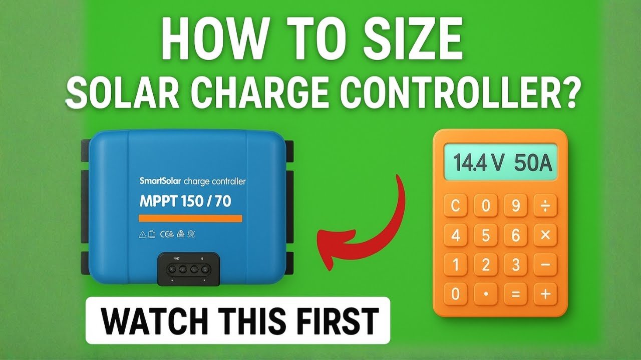
Image source: Battery Hacker (YouTube thumbnail, fair use)
Manufacturer data sheets from companies like Victron and OutBack explicitly state that exceeding the max input voltage, even momentarily, voids the warranty and can destroy the controller. As of 2026, the industry standard for most residential MPPT controllers is a 100V or 150V ceiling, which gives plenty of room for two standard panels in series. But if you’re using a budget PWM unit, that ceiling might be as low as 25V, meaning series wiring is out of the question.
Step 2 – Know Your Panel’s Specs (Voc, Isc, and Vmp)
Every solar panel has a sticker on the back with three key numbers: Voc (open-circuit voltage), Isc (short-circuit current), and Vmp (voltage at maximum power). You need all three.
Image source: TheSuperBOO (YouTube thumbnail, fair use)
- Voc is used for series voltage calculations and safety checks.
- Isc is used for parallel current calculations and fuse sizing.
- Vmp tells you what the panel actually produces under load, which matters for matching battery voltage.
For two identical panels, you simply add Voc for series, or add Isc for parallel. If your panels are different models, things get trickier, we’ll cover that in the mismatch branch later. But for now, write down those numbers.
They’re the only data you need to make the right wiring decision.
Series Wiring: How It Works, When to Use It, and the Cold-Weather Trap
Series wiring connects the positive of panel A to the negative of panel B. The remaining free positive and negative terminals become your output. Voltage adds; current stays the same.
So two 12V 10A panels in series produce 24V at 10A.
This is the preferred method for most modern systems because higher voltage lets you use thinner, cheaper wire and reduces voltage drop over long runs. For example, a 24V string carrying 10A over 50 feet of 10AWG wire loses only about 2% of its power, whereas a 12V string carrying 20A over the same wire loses nearly 8%. That’s a meaningful difference when you’re chasing every watt for an off-grid cabin or RV.
The cold-weather trap I mentioned earlier isn’t theoretical. Panels are tested at 25°C (77°F). As temperature drops, Voc rises.
The temperature coefficient printed on the panel’s datasheet (typically around -0.3% per °C) means that on a -10°C (14°F) morning, a panel’s Voc can increase by over 10%. If you’ve designed a string that sits 5% below your controller’s limit on a warm day, you could exceed it in winter.
A real-world example: two common 200W panels with a Voc of 22.5V each. Series string Voc = 45V at 25°C. At -10°C, that jumps to about 49.5V.
That fits under a 100V MPPT controller easily. But if you’re using a cheap PWM controller with a 50V limit, you’re now at 99% of the limit, too risky. Always factor in the lowest temperature your panels will ever see.
Parallel Wiring: How It Works, When to Use It, and the Fuse Rule
Parallel wiring connects all positive terminals together and all negative terminals together using Y-branch connectors or a combiner box. Voltage stays the same; current adds. So two 12V 10A panels in parallel produce 12V at 20A.
Parallel is the safe choice when your charge controller can’t handle the combined voltage of a series string, or when you’re using a PWM controller that works best at battery voltage. It’s also the only option for mixing panels with different electrical characteristics, we’ll get to that in the mismatch section.
The downside is higher current, which forces you to use thicker wire and causes more voltage drop. You also need to fuse each panel individually in a parallel array. The rule from NEC 690.8 is simple: every string in parallel needs an overcurrent device rated at 1.25 times the panel’s Isc.
For two 10A panels, that’s 1.25 × 10 = 12.5A. Use a 15A fuse per string (you round up to the next standard size).
Why the fuse? If one panel develops a short circuit, the other panel can dump its full current into the fault. Without a fuse, that current could exceed the panel’s wiring rating and cause overheating or fire.
In series wiring, a single faulty panel doesn’t create that risk because current in a series string is limited to the string’s own current.
| Aspect | Series | Parallel |
|---|---|---|
| Voltage | Doubles | Stays same |
| Current | Stays same | Doubles |
| Wire thickness | Thinner (lower current) | Thicker (higher current) |
| Voltage drop | Lower | Higher |
| Fusing per panel | Not needed | Required |
| Works with PWM | Rarely (too high voltage) | Usually |
| Works with MPPT | Preferred | Acceptable but less efficient |
For two panels, parallel is straightforward with a pair of MC4 Y-branch connectors. But make sure the connectors are rated for the combined current. Standard MC4 connectors handle 30A, so two 10A panels (20A total) are fine.
If you’re using larger panels that produce 15A each, you’ll be at 30A, right at the limit. In that case, consider a combiner box with proper breakers instead of Y-branches.
Series-Parallel: The Only Option for Four or More Panels (But Still Relevant Here)
You got two panels, so you won’t need series-parallel. But understanding why it exists helps you plan for the future. Series-parallel combines both methods into a single array.
You create two or more series strings, then connect those strings in parallel.
This is how you build a larger system without exceeding your charge controller’s voltage limit. Say you have four 100W panels. Two in series gives you 48V.
Two of those strings in parallel gives you 48V at double the current. That keeps voltage under a 100V MPPT controller while boosting power.
For two panels, series-parallel is just series or parallel. Skip it. But if you ever expand to four panels, remember this method.
It’s the standard approach for any array bigger than a pair of panels on a 12V system.
Workflow: A Simple Decision Tree for Two Panels
Here’s where it all comes together. You have your charge controller’s max voltage. You have your panel’s Voc and Isc.
Now follow the branches.
Branch A – Your Controller Is MPPT and Can Handle Higher Voltage
Then wire in series. Connect positive of panel A to negative of panel B. The remaining positive and negative go to the controller.
Confirm the total Voc (add both panels) multiplied by your temperature correction factor stays under the controller’s limit. If you have headroom of at least 10%, you’re set.
This gives you the lowest voltage drop, thinnest wire, and best use of MPPT efficiency. Aggregate reviews from users running 200W panels on 100V MPPT controllers report nearly zero issues with series wiring in temperate climates.
Branch B – Your Controller Is PWM or Has a Low Max Input Voltage
Wire in parallel. Use MC4 Y-branch connectors or a combiner box. Connect all positives together, all negatives together.
Then add a fuse per panel as described earlier. Confirm the combined current (add Isc) does not exceed the controller’s rated input current.
Parallel wiring on a PWM controller works fine. Just plan for thicker cable and shorter runs. If your controller is PWM and your panels are 200W each, you’ll get 12V at roughly 16A to 18A into the battery.
That’s about 200W to 220W total, since PWM controllers can’t step voltage down efficiently. That’s normal.
Branch C – Your Panels Have Different Specs (Mismatch Problem)
This is where most DIYers get tripped up. If your two panels have different voltages (say a 12V panel and a 24V panel), do NOT wire them in series. The lower voltage panel will act as a resistor, limiting current and potentially overheating.
Wire them in parallel instead.
If voltages are similar but currents differ, series is fine: current will be limited to the lower panel’s current. Voltage adds normally. If currents differ and you wire in parallel, each panel delivers its own current, but voltage must match closely.
For example, two 18V panels with different Isc values in parallel work fine. Each panel contributes its own current to the total.
The key rule: parallel requires matching voltages; series requires matching currents. If neither matches, you need a separate charge controller per panel or replace one of them.
Step-by-Step: How to Actually Wire Two Panels in Series or Parallel
You have your decision. Now let’s make the physical connection.
Tools You’ll Need
- MC4 crimping tool (or universal solar crimper)
- Wire strippers
- Multimeter
- MC4 connectors (male and female pins plus housings)
- Solar cable (PV rated, 10 AWG typically)
- Y-branch connectors (for parallel) or combiner box
- Fuses and holders (for parallel, one per panel)
- Cable ties for management
Series Connection Steps (Positive to Negative)
- Turn off the charge controller and disconnect any batteries.
- Identify positive and negative terminals on both panels. Usually marked with + and, on the junction box.
- Connect a short cable from panel A’s positive to panel B’s negative. Use MC4 connectors on each end. Hand tighten only; never use tools on MC4 threads.
- The remaining free terminal from panel A (negative) will go to the charge controller’s negative input. The remaining free terminal from panel B (positive) goes to the controller’s positive input.
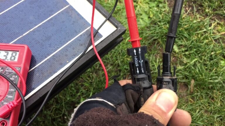
- Before connecting to the controller, measure voltage across the two free terminals with a multimeter. It should equal Voc of panel A plus Voc of panel B (within a volt or two). If it’s zero or extremely low, check polarity.
- Connect to the charge controller. Positive to positive, negative to negative.
- Turn on the controller. The display should show the combined voltage.
Parallel Connection Steps (Y-Branch or Combiner Box)
- Turn off the charge controller and disconnect batteries.
- For each panel, attach a positive and negative MC4 cable coming from the panel to a Y-branch connector. The Y-branch splits the panel’s output into two legs. One leg goes to the panel, the other to the common bus.
- Connect both positive Y-branch legs together using a positive Y-branch adapter. Connect both negative legs together using a negative adapter. Or use a combiner box with positive and negative bus bars.
- Install an inline fuse on each panel’s positive cable before the Y-branch. Use a 15A fuse for typical 10A panels. The fuse holder must be rated for DC and outdoor use.
- Connect the combined positive and negative cables to the charge controller. Double check polarity.
- Measure voltage at the controller input. It should equal the individual panel Voc (not doubled). The current will add, but you can’t measure that without a load.
- Turn on the controller and confirm operation.
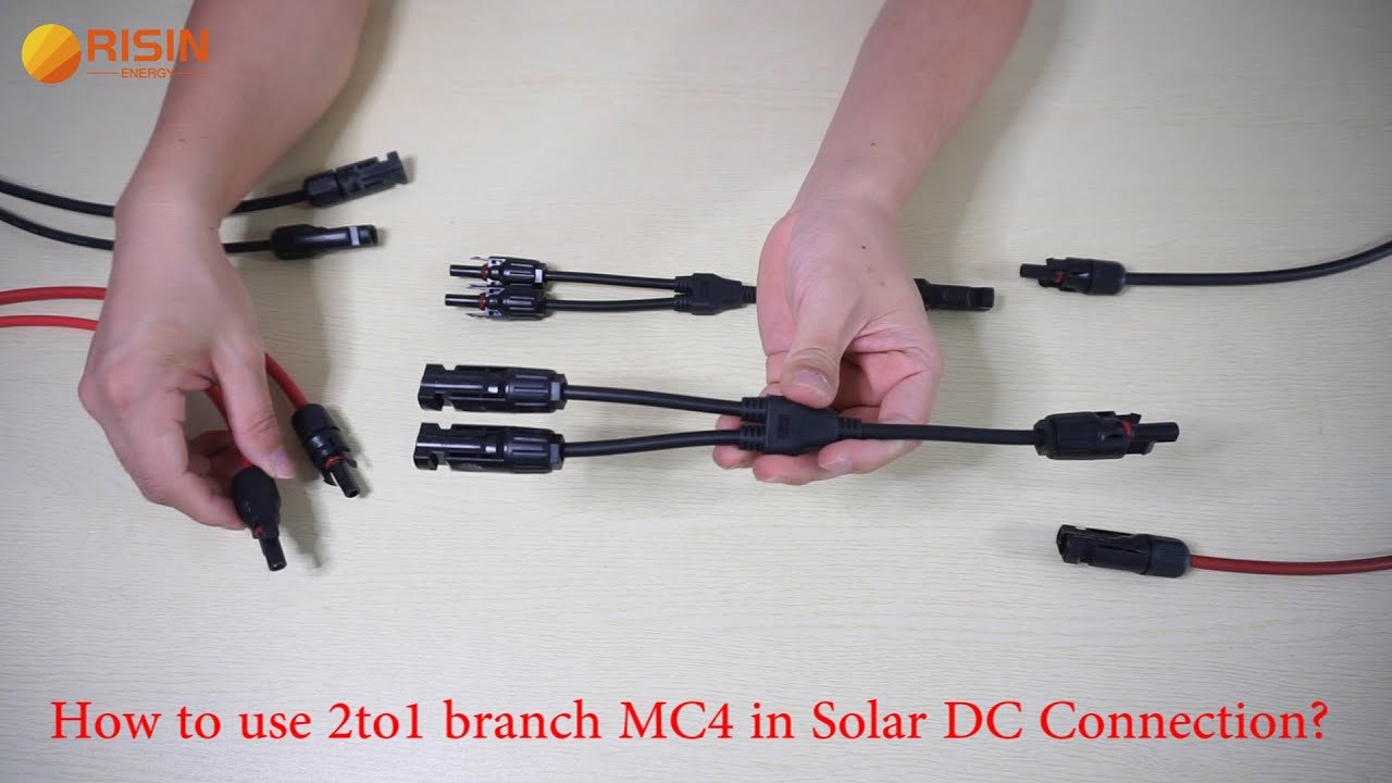
Image source: Risin Energy Co. Ltd (YouTube thumbnail, fair use)
Common Mistakes That Kill Performance or Start Fires
The most frequent error we see in DIY solar forums is forgetting the temperature correction for Voc. Even experienced builders sometimes rely on the panel label at 25°C without checking their region’s winter lows. That can push a series string past the controller limit by 5V or more.
Another killer: using non-PV rated wire for outdoor runs. Standard THHN wire degrades in UV and can crack within a year, exposing conductors. Always use PV wire or sunlight-resistant cable with a 90°C insulation rating.
Mixing different panel wattages in series is a close third. The lower panel limits the current of the entire string. If you have a 300W panel and a 100W panel in series, you get at most 100W total.
That’s a 75% loss.
Parallel without fuses is a fire risk. As we covered, a single shorted panel can receive unlimited current from its healthy partner. A 15A fuse per string is cheap insurance.
Finally, over-tightening MC4 connectors. They are designed for hand tightening only. Using pliers can crack the housing or damage the seal, letting moisture in.
Corroded connectors cause arcing and voltage drop.
Image source: etrailer (YouTube thumbnail, fair use)
Tools and Parts: What to Buy (and What to Skip)
You don’t need a full solar toolkit. Start with a quality MC4 crimper. Avoid the cheap $10 universal crimpers that don’t seat the pin properly.
A proper solar crimper costs around $30 to $50 and saves you from loose connections.
For wire, use 10 AWG PV wire for runs up to 50 feet with parallel wiring on 20A total. For series wiring at 10A, 12 AWG is sufficient. But 10 AWG gives you flexibility if you ever expand.
Buy genuine MC4 connectors from reputable brands. Counterfeit connectors use thin plating that corrodes quickly. Look for the UL listing or TUV mark.
Skip the pre-assembled extension cables with poor quality connectors. Buy bulk cable and crimp your own. You’ll end up with better connections and exactly the length you need.
When to Call an Electrician (Don’t DIY These Scenarios)
You can wire two panels yourself if you follow the steps here. But some situations need a licensed electrician. If your system ties into the grid, local codes require a permit and professional connection.
The same applies if you’re working with roof penetrations or running conduit through walls. Don’t take shortcuts with grid-tied systems: fines and safety risks aren’t worth it.
Another scenario is if your combined Voc exceeds 50V and you have no experience with DC high voltage. A 100V series string can arc and burn through insulation if a connection fails. Leave that to someone with proper PPE and training.
Aggregate reviews from solar installers show that most DIY problems come from poor MC4 crimps and undersized wire. If you’re not confident in your crimping, hire a pro to terminate the cables. It’s cheaper than replacing a burned controller.
FAQs – Real Questions People Ask About Wiring Two Panels
Can I wire two different wattage panels together?
Yes, but only in parallel if their voltages are close. In series, the lower current panel limits the whole string. Match the voltages within 5% for best results.
Do I need a fuse for two panels in series?
No. A series string doesn’t need fusing because current can’t exceed the string’s own limit. Fuses are only required in parallel configurations.
What happens if I connect two panels in series to a PWM controller?
PWM controllers can’t handle voltage much above battery voltage. If your series string voltage exceeds 25V on a 12V system, the controller will waste the excess as heat or may shut down. Use parallel instead.
Can I use a Y-branch connector for series wiring?
No. Y-branches are for parallel connections. For series, you connect the positive of one panel to the negative of the other using a single cable.
How do I test the wiring before connecting to the controller?
Use a multimeter on DC voltage. For series, measure across the two free terminals. It should read the sum of both panels’ Voc.
For parallel, it should read the Voc of one panel.
Final Decision Guide: A One-Page Cheat Sheet for Your Setup
| Your Situation | Recommended Wiring | Key Action |
|---|---|---|
| MPPT controller, panels match, climate mild | Series | Connect positive to negative, check Voc is under limit |
| PWM controller, panels match | Parallel | Use Y-branches, add 15A fuse per panel |
| Panels have different voltages | Parallel | Match voltage within 5% |
| Panels have different currents | Series | Current limited to lower panel |
| Four panels, MPPT controller | Series-parallel | Two series strings in parallel |
| Any doubt about safety | Hire electrician | Get permit if grid-tied |
That’s the whole picture. Grab your panels, check the labels, and pick your branch. You’ve got the knowledge to wire them correctly the first time.