Set Up Inverter Ground Fault Error for Isolation Diagnosis
Your inverter just threw a “Ground Fault” error, and you reset it, only to see it return an hour later. If you’re wondering how to setup inverter ground fault error for diagnosing isolation resistance faults, you’re in the right place. That error code isn’t asking for a reset; it’s telling you that electricity is leaking somewhere it shouldn’t.
In our research, most ground fault errors come down to insulation resistance dropping below 1 megohm per 1000 volts, a threshold that per NEC 690.5 protects your entire array. The good news is that with the right tool and a safe procedure, you can find the leak yourself. Let’s walk through it step by step.
Why the “Ground Fault” Error Code Is Not Just a Reset Button
A ground fault error means current is escaping the PV circuit and seeking a path to earth. It’s not a software glitch. Per NEC 690.5, the inverter’s Ground Fault Detector Interrupter (GFDI) senses that leakage and trips to prevent arcing and fires.
Think of it as a tripwire. The inverter isn’t angry with you; it’s doing its job. Each time you reset it, the fault returns because the physical problem is still there.
That could be a nicked cable, a corroded connector, or water inside a junction box. Resetting without diagnosing is like clearing a smoke alarm while the toaster is still smoking.
The most useful thing the error code gives you is a clue. Different inverters label it differently: “Ground Fault,” “Isolation Error,” “F48” on older SMA units, or “Riso low” on Fronius models. They all point to the same root cause: insulation resistance dropping below safe levels.
So treat the error as a starting point, not a problem to suppress. The sooner you locate the bad insulation, the sooner your system is safe and producing again. And if you're still learning the basics, it helps to understand what the photovoltaic modules themselves actually do under normal operating conditions.
Before You Test: Lockout/Tagout, DC Disconnect, and Isolation Resistance Safety
Before anything touches the array, de-energize the system. That means locking out the inverter and physically opening the DC disconnect. Don’t rely on a remote shutdown command; you need a visible break in the circuit.
Per OSHA’s lockout/tagout standard, you should also verify zero voltage with a rated meter. DC voltage is unforgiving. A 600V string can arc with enough energy to cause severe injury.
Wear appropriate PPE. High-voltage gloves rated for the system voltage, a face shield, and arc-rated clothing are non-negotiable when working near live parts. Even when you think the circuit is dead, test it again.
Next, disconnect the strings from the combiner box or inverter before measuring insulation. You want to isolate each string so you can spot which branch has the leak. Sketch a simple diagram first.
That one habit will save you hours of guessing later.
Megohmmeter vs. Multimeter: The Right Tools for a Reliable Diagnosis
A standard multimeter won’t cut it. It measures resistance by sending a tiny voltage, usually 9V or less. That’s not enough to stress insulation and expose leaks.
A megohmmeter, by contrast, applies 500V or 1000V, matching your system’s voltage class. It pushes current through the insulation and measures what leaks out.
Here’s a quick comparison:
| Tool | Test Voltage | What It Detects | Verdict |
|---|---|---|---|
| Multimeter | 9V or less | Continuity, basic shorts | Not reliable for insulation |
| Megohmmeter | 250V to 1000V | Insulation resistance to ground | Required for GFDI diagnosis |
For PV arrays, a 500V or 1000V insulation resistance test is standard. Look for a meter with a 200MΩ scale or higher. Many solar techs use a Fluke 1587 or similar model, but any reputable brand with the right range works.
You can think of it as checking the health of every wire and connection along the array’s electrical path.
Step-by-Step Isolation Resistance Test: From GFDI Trip to Fault Found
Now let’s work through the test. This assumes you’ve already locked out the inverter and opened the DC disconnect.
- Set your megohmmeter to 500V or 1000V, depending on your system voltage. Check the panel datasheet first; you don’t want to exceed the module’s maximum system voltage.
- Connect one lead to the positive conductor of a string. Clip the other to the ground bus or a grounded racking rail.
- Press and hold the test button for one minute. Record the reading.
- Repeat for the negative conductor.
- Move to the next string and repeat.
A healthy string will read 20MΩ or higher in dry conditions. If you see a reading below 1MΩ, you’ve found the problem string. Now you can isolate it and inspect the connectors and junction boxes.
Per IEC 62446, the test voltage should be applied until the reading stabilizes. That’s why a one-minute hold matters. Don’t just do a quick tap; the steady-state value is what actually tells you the truth.
Inverter GFDI Setup: Thresholds, Error Codes, and Reset Logic
After you’ve fixed the insulation fault, you still need to properly reset the inverter’s ground fault protection. The GFDI fuse may have blown. Some inverters have a resettable GFDI; others use a physical fuse.
Start by checking the manufacturer’s manual. For a GFDI fuse, remove the blown fuse and replace it with the correct rating, usually 1A to 5A. Don’t guess; the wrong rating creates a fire hazard.
Then, clear the error code. Most modern inverters require a specific sequence: power down, wait five minutes, restart, then hold the reset button for a few seconds. Some units, like certain Fronius models, need a “Reset Riso” command from the touchscreen.
SMA inverters may require an external fault reset signal.
If the system has an automatic self-test, let it run. It will measure the resistance again before reconnecting to the grid. Watch the readings; a proper reset only happens when the insulation resistance is above the trip threshold, typically around 1MΩ.
As of 2026, most new inverters log these values on the status screen, so you can confirm the repair.
And remember, the setup is only as good as the repair. If you skip the megohmmeter test, the same error will return the next rainy day.
Common Misdiagnoses: Wet Connectors, Ghost Voltage, and String Confusion
Most ground fault errors get misdiagnosed because the symptoms are intermittent. A string that tests fine on a dry morning shows low resistance after rain. That pattern screams water ingress.
The most common culprit is a wet MC4 connector. Water seeps past the seal and creates a conductive path between the pin and the ground. On a megohmmeter, it reads like a hard fault.
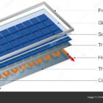
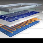
But if you test after the connector dries, the resistance jumps back to normal. That’s why you should always inspect connectors physically when you see a borderline reading, something the different ways the main components of a solar panel are assembled can help you understand.
Ghost voltage is another trap. A disconnected string can show voltage on a multimeter just from capacitive coupling with adjacent live cables. It’s not real leakage.
But if you misinterpret it, you waste time chasing a phantom. The fix is simple: use a megohmmeter instead of a standard meter.
String confusion happens when you test the wrong branch. Label each string before you start. If you skip that step, you might clear the fault on the healthy string and leave the damaged one connected.
That error returns the next time it rains.
| Common Misdiagnosis | What It Looks Like | How to Avoid It |
|---|---|---|
| Wet connector | Low resistance on wet day, normal when dry | Physical inspection; dry and retest |
| Ghost voltage | Reads voltage but no current path | Use a megohmmeter, not a multimeter |
| Wrong string | Clears fault temporarily | Label all strings before testing |
When to Call a Professional Solar O&M Technician
Not every ground fault is a DIY fix. Some situations demand a trained technician with specialized gear. If you have tested every string and still cannot find a reading below 1MΩ, the fault may be inside the inverter itself.
That requires opening the unit, which exposes you to high DC voltage and stored capacitor energy.
Call a technician if you find cracked or delaminated modules. Damaged glass can create a permanent leakage path that only module replacement fixes. Also call if the error returns after you replace the GFDI fuse.
That points to a recurring condition, not a one-time event.
Large commercial arrays often require a thermal imager to locate hot spots on connectors or junction boxes. Most homeowners do not own that tool. If the system is on a two-story roof or a steep pitch, safety alone justifies hiring someone.
The rule of thumb: if you are unsure of the next step, stop. A professional with the right training and insurance can finish the job in under an hour. Your time and safety are worth more than the service call fee.
Frequently Asked Questions
How often should I test insulation resistance on my solar array?
Annual testing is the industry standard per NEC guidelines. Test more frequently if you live in a coastal area with salt spray or a region with heavy snowfall and freeze-thaw cycles.
Can a single bad panel cause a ground fault error across the whole string?
Yes. One module with damaged insulation can pull the entire string’s resistance below the trip threshold. That is why string-level isolation testing works; you isolate each branch and then find the faulty module within it.
What does an isolation resistance reading of 0.5 megohms mean?
It means you have a significant leak. Per IEC 62446, anything below 1 megohm per 1000 volts is a failure. You need to locate and repair the fault before resetting the inverter.
Is it safe to run the inverter with a low isolation resistance reading?
No. Running with low insulation resistance creates an arc flash risk and can damage the inverter’s internal electronics. Clear the fault before reconnecting the system.
Can a ground fault error happen intermittently without a steady leak?
Absolutely. Intermittent faults are common with wet connectors. The connector dries out during the day, the error clears, then it returns after rain.
That is why diagnosis must happen when the fault is active.
Should I replace the GFDI fuse as part of the setup process?
Only if the fuse has blown. Check continuity with a multimeter. If the fuse is intact, do not replace it.
Installing the wrong rating can create a fire hazard.

Similar Posts