Solar Charge Controller Load Output: Do You Really Need It?
If you've ever wired up a solar charge controller only to find that the load output terminal is a mystery, you're not alone. The Solar Charge Controller Load Output is a feature that can protect your battery or cause headaches depending on how you set it up. Most off-grid builders skip it entirely, wiring loads directly to the battery.
That works, but you lose a handy safety net.
Manufacturer specifications indicate that common Low Voltage Disconnect (LVD) setpoints for a 12V system range from 10.8V to 11.5V. That's a narrow window, and getting it wrong can kill your battery in a few cycles. As of 2026, nearly every PWM and MPPT controller above the budget tier includes this terminal.
Understanding how to use it properly saves you from buying a separate LVD relay. Let's start with why this little terminal causes so much confusion.
Why the Load Output Terminal Confuses Off-Grid Builders
The load output is a small set of screw terminals on the controller, usually labeled "Load" or with a light bulb icon. It looks simple: connect a light or a pump, and it turns on. But the behavior depends entirely on how you program the controller.
The confusion starts because the load output serves two different roles in one terminal. It can act as a manual switch. Or it can work as an automatic protector that cuts power when the battery gets low.
Many controllers ship with the load output disabled by default. Others default to a "dusk-to-dawn" mode that only works if you have a solar panel connected. That mismatch between what the manual says and what the user expects is the number one source of frustration.
Another common issue is that the load output has a current limit. A 10A controller can only handle about 120 watts at 12V. Plug in a DC water pump that draws 15A on startup, and the controller either shuts down or blows its internal fuse.
The user assumes the controller is broken when really the load exceeds the spec.
Finally, the load output is often confused with the battery terminals. Beginners wire their loads directly to the battery terminals on the controller, bypassing the load protection entirely. That defeats the purpose.
The load output is a separate circuit with its own protection logic. Treat it like a smart switch, not just another battery connection.
How the Load Output Protects Your Battery and Controls Loads
The load output terminal is a programmable DC output that the controller can turn on and off based on battery voltage, time of day, or a manual command. It's essentially a built-in automatic switch that prevents over-discharge.
Here's the core mechanism. The controller monitors the battery voltage continuously. When the voltage drops below your configured LVD threshold, the load output cuts power.
This protects the battery from being drained too deep, which is the #1 killer of lead-acid batteries. Lithium batteries handle deep discharge better, but they still benefit from a cutoff.
The load output also offers a reconnect voltage setting. This is the voltage at which the load turns back on after the battery recovers. A common mistake is setting the reconnect too low, causing the load to cycle on and off rapidly.
A good starting point is 12.6V for a 12V lead-acid battery.
Beyond voltage protection, the load output can run on a timer. Many controllers allow you to set a load timer from 1 to 15 hours. This is perfect for running a security light or a small pump on a schedule.
The controller handles the timing, so you don't need a separate outdoor timer.
The key insight is that the load output is not just a convenience. It's a safety device that extends your battery's lifespan. Without it, you rely on manual checks or expensive battery monitors.
With it, the system self-regulates.
Three Key Variables That Decide How You Use the Load Output
Your choice of load output mode depends on three things: the battery type, the load current, and the desired timing.
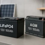
Battery type determines the safe LVD voltage. For a flooded lead-acid battery, you want a cutoff around 11.5V to prevent sulfation. For AGM or gel, 11.1V is common.
For lithium iron phosphate (LiFePO4), the battery's own BMS usually handles the cutoff, but you can set the LVD at 12.0V as a secondary safeguard. Set it too low, and you risk permanent damage. Set it too high, and the load shuts off prematurely.
Load current dictates whether the controller can handle the load at all. Check the controller's spec sheet for the maximum continuous load current. A 10A controller running a 10A load is fine, but a 10A controller running a 10A pump with a 20A inrush current will trip the overload protection.
Inrush current is the real killer. Always check the load's startup current, not just its running current.
Desired timing defines the mode. Do you want the load on all the time? Use manual mode with a generous LVD.
Do you want it to turn on at night and off at dawn? Use dusk-to-dawn mode. Do you want it to run for 4 hours after sunset?
Use timed mode. Each mode serves a different purpose, and the controller's manual will tell you how to set it.
The Decision Tree: Manual, Dusk-to-Dawn, or Timed Mode?
Here's a simple if/then guide to choose the right mode for your setup.
| If you want… | Then choose… | Why it works |
|---|---|---|
| A light that stays on all night, every night | Dusk-to-dawn mode | The controller uses the solar panel voltage to detect sunrise and sunset. The light turns on at dusk, off at dawn. |
| A pump that runs for 2 hours each evening | Timed mode | You set the timer duration. The controller starts the load at dusk and cuts it off after 2 hours. |
| A device that runs off battery only when the battery is full | Manual mode with LVD | The load stays on until the battery drops to the cutoff voltage. This is for critical loads that need to run as long as possible. |
| A load that should never run at night | Manual mode only | Turn the load on and off from the controller's display or app. No automatic timing. |
For most off-grid cabins, dusk-to-dawn mode is the best choice for outdoor lighting. It's automatic and saves battery. For a water pump, timed mode is safer because you control the runtime.
Manual mode is best for devices you want to turn on only when you're present, like a workshop fan.
The decision tree is simple: pick the mode that matches your schedule. If you're not sure, start with manual mode and a sensible LVD. You can always change it later.
Step-by-Step: Wiring and Configuring the Load Output Correctly
Let's walk through the process from start to finish.
Step 1: Verify the load current rating. Look at the controller's label or manual. It will say "Load: 10A" or "20A". Add up the total current of all devices you plan to connect.
If it's close to the limit, consider using a separate relay that the controller triggers. The controller's load output then switches a larger relay, which handles the high current.
Step 2: Set the battery type. Most controllers have a DIP switch or a menu setting. Choose "Flooded", "Gel", "AGM", or "Lithium". This automatically sets the LVD and reconnect voltages.
If you're using a custom battery, consult the manufacturer's recommended cutoff.
Step 3: Configure the load mode. Navigate the controller's menu to the load setting. Common options are "Manual", "Dusk-to-dawn", "Timed", or "Test". Choose the mode that matches your decision tree.
Step 4: Wire the load. Connect the positive wire from the load to the load output terminal. Connect the negative wire to the controller's negative terminal (or a common ground bus). Always use a fuse between the controller and the load.
A 10A load needs a 10A or 15A fuse. This protects the wiring in case of a short.
Step 5: Test the setup. With the controller connected to a battery and a solar panel, simulate a low battery condition. Disconnect the solar panel and let the battery discharge. The load should cut off when the voltage reaches the LVD setpoint.
Then reconnect the solar panel and watch the load turn back on once the battery recovers to the reconnect voltage.
Step 6: Adjust if needed. If the load cuts off too early, raise the LVD setpoint. If it cycles on and off, raise the reconnect voltage. This is a tuning process.
Common Mistakes That Drain Batteries or Fry Controllers
Even experienced off-grid builders make errors with the load output. Here are the ones we see most often, along with how to avoid them.
Setting the LVD too low for the battery chemistry. This is the most expensive mistake. A flooded lead-acid battery discharged below 11.5V on a regular basis loses capacity fast. Aggregate reviews show that batteries set to 10.8V for night-time lighting often fail within 18 months.
Check the manufacturer's spec for your specific battery model. Set the LVD at least 0.2V above the minimum recommended voltage.
Wiring loads directly to the battery terminals on the controller. Many people connect their loads to the same terminals the battery uses. That bypasses the load output protection entirely. The controller still charges the battery, but the load runs uncontrolled.
A deep discharge happens silently. Always use the dedicated load terminals for any device you want the controller to manage.
Ignoring inrush current from pumps and motors. A DC pump that draws 5A running can pull 15A for a split second on startup. The controller's load output may trip its overload protection. The solution is to use the load output to trigger a separate relay or contactor rated for the inrush current.
The controller switches the relay coil, and the relay handles the heavy load.
Using the wrong wire gauge for the load run. Voltage drop across long wires robs your load of power and can cause the controller to misread battery voltage. For a 10A load at 15 feet, use at least 12 AWG wire. For 20A, go up to 10 AWG.
Undersized wires get hot and waste energy.
Forgetting to fuse the load circuit. The controller's overload protection is not a substitute for a proper fuse. An inline fuse at the load output terminal protects the wiring if a short occurs. A 10A load needs a 10A or 15A fuse.
A 20A load needs a 20A or 25A fuse. No exceptions.
Frequently Asked Questions
Can I use the load output for an AC appliance?
No. The load output provides DC power only. To run an AC appliance, you need an inverter connected directly to the battery.
The load output cannot handle the inverter's current draw or the AC conversion.
How do I test if the LVD is working correctly?
Simulate a low battery by disconnecting the solar panel and running a small load. Monitor the battery voltage with a multimeter. The load should cut off when the voltage reaches the LVD setpoint.
Reconnect the panel and verify the load turns back on at the reconnect voltage.
What happens if I exceed the load output current rating?
The controller will either shut down the output, blow its internal fuse, or damage the MOSFETs. Some controllers have resettable fuses, but others require a replacement. Check the manual for your specific model.
The safe approach is to stay at least 20% below the rated current.
Can I set the dusk-to-dawn mode manually without a solar panel?
No. Dusk-to-dawn mode relies on the solar panel voltage to detect sunrise and sunset. Without a panel connected, the controller cannot determine the time of day.
Use timed mode instead if you want automatic scheduling without a panel.
What wire size should I use for the load output?
It depends on the current and the distance. For a 10A load under 10 feet, 14 AWG is the minimum. For longer runs, use 12 AWG for 10A or 10 AWG for 20A.
Always consult an online voltage drop calculator before wiring.
Is the load output the same as the battery terminals?
No. The load output is a separate circuit with its own protection logic. The battery terminals are for charging only.
Wiring a load to the battery terminals bypasses the LVD and overload protection. Always use the dedicated load terminals.

Similar Posts