How to Wire a 5000W Inverter: Step-by-Step
How to Wire a 5000 Watt Inverter? It’s one of those jobs that looks simple on paper but gets scary the second you see the cable size. The biggest mistake people make is ignoring the actual current draw.
A 5000 watt inverter pulling full load on a 12V system can exceed 500 amps. That’s more than enough current to melt undersized wire and start a fire if you connect it wrong.
In our research, the most common failure point is picking cables based on wattage instead of amps. Manufacturer specifications indicate that a 12V 5000W inverter at full continuous load requires at least 4/0 AWG cable. For a 48V system, the same 5000W drops to around 120 amps and needs just 4 AWG.
That single difference determines whether your installation is safe or dangerous. Let’s walk through what you need to know before you touch a single wire.
Quick Answer
To wire a 5000 watt inverter, first calculate your system voltage. Use 4/0 AWG for 12V, 2/0 AWG for 24V, and 4 AWG for 48V. Install a Class T fuse within 12 inches of the battery positive terminal.
Connect negative first, then positive. Torque all terminals to manufacturer spec. Test polarity before powering on.
Why Getting This Wiring Wrong Can Be Dangerous (The One Number That Changes Everything)
The single number that matters most is amps, not watts. At 5000 watts continuous load, a 12V system pulls around 500 amps. That’s the same current that feeds an entire house main breaker.
If you use wire rated for 200 amps, it becomes a heating element. The insulation melts. Then you get a short circuit, a flash, and potentially a fire.
Per the National Electrical Code (NEC) and ABYC standards, DC circuits at these current levels require oversized conductors and fast-acting overcurrent protection. A Class T fuse rated at 500 amps is the standard for 12V 5000W installations. Without it, a short in the inverter or cable can arc continuously and ignite nearby materials.
The danger isn’t just theoretical. Aggregate user reviews on battery and inverter forums describe melted terminals and burnt wires from people skipping the math. The good news is that proper design eliminates the risk.
The Math You Actually Need: Voltage, Amps, and Wire Sizing
The formula is simple: Amps = Watts ÷ Volts. For a 5000W inverter:
| System Voltage | Full Load Amps (continuous) | Minimum Wire Gauge (up to 5 ft) | Recommended Fuse (Class T) |
|---|---|---|---|
| 12V | 416–500 | 4/0 AWG | 500A |
| 24V | 208–250 | 2/0 AWG | 250A |
| 48V | 104–125 | 4 AWG | 150A |
These figures assume a 96% efficiency (most quality inverters lose 4, 8% as heat). Account for surge loads too. Many inverters can double output for a few seconds to start motors.
Your wire must handle that surge without voltage drop or overheating.
Voltage drop is the hidden killer of performance. If your battery bank is more than 5 feet away, upgrade to the next thicker gauge. For example, a 12V system at 15 feet needs 2 × 4/0 AWG cables paralleled or move the inverter closer.
Our recommendation: keep cable runs under 5 feet whenever possible. If you have the flexibility, go with a 48V system. The wire cost is dramatically lower and the installation is much easier.
Step-by-Step: Wiring Your 5000 Watt Inverter the Right Way
Step 1: Gather materials and measure twice.
You need the correct gauge cables, a Class T fuse holder with fuse, a battery disconnect switch, ring terminals, a torque wrench, and a multimeter. Confirm your inverter’s DC input terminals accept the lug size you plan to use (usually 3/8 or 5/16 inch).
Step 2: Disconnect the battery bank.
Remove the negative cable first, then positive. Never work on a live battery bank at these currents. A dropped wrench across the terminals creates a dead short and can weld itself in place.
Step 3: Mount the inverter within 3 to 6 feet of the battery.
Place it in a dry, ventilated area. Keep it away from battery hydrogen off-gassing. Do not mount it directly above or below the battery.
Step 4: Install the fuse on the positive cable.
Position the fuse holder within 12 to 18 inches of the battery positive terminal. This protects the entire length of cable from the battery to the inverter. If the cable shorts against the chassis, the fuse blows immediately.
Step 5: Connect the negative cable first.
Attach one end to the battery negative terminal, the other end to the inverter negative terminal. This reduces the chance of accidental shorts while you handle the positive cable.
Step 6: Connect the positive cable to the inverter.
Attach the fused end to the battery positive terminal, then the other end to the inverter positive terminal. Do not connect the inverter positive to the battery until after the fuse is in place.
Step 7: Torque every terminal to spec.
Use a torque wrench set to the value in your inverter manual. Typical values are 8 to 12 foot-pounds for inverter terminals and 10 to 15 foot-pounds for battery terminals. Overtightening strips threads.
Undertightening creates resistance and heat.
Step 8: Ground the inverter chassis.
Run a wire of the same gauge from the inverter grounding lug to your system’s chassis ground. This prevents shock if an internal fault occurs.
Step 9: Double-check polarity.
Use your multimeter to confirm voltage polarity at the inverter terminals. Reverse polarity can damage the unit permanently.
Step 10: Power on and load test.
Reconnect the battery. Turn on the inverter with no load. Check for unusual sounds or smells.
Then apply a small load first (e.g., 200W) and measure voltage at the inverter terminals under load. It should not drop more than 3% from the battery voltage.
Five Mistakes That Will Melt Your System (and How to Avoid Them)
1. Using wire rated for lower amperage.
The biggest mistake. At 5000W on 12V, you need 4/0 AWG. Using 2 AWG will work for a few minutes, then the insulation bubbles.
Always oversize by at least one gauge for safety.
2. Fusing the negative cable instead of the positive.
A fuse on the negative does not protect against a positive-to-chassis short. Always fuse the positive line within inches of the battery.
3. Skipping the battery disconnect switch.
Without a switch, you can’t easily kill power to the inverter without pulling the fuse. This makes maintenance dangerous. Install a heavy-duty switch rated for your system’s full load amps.
4. Soldering terminals instead of crimping.
Soldered joints crack under vibration and heat, especially at high current. Military and marine standards require crimped connections. Use a hydraulic crimper with tinned copper lugs.
5. Not accounting for voltage drop.
Long battery cables kill efficiency and cause heat. If your run exceeds 5 feet, recalculate with a voltage drop calculator. Many users find they need one size thicker than the minimum for 3% drop.
When You Should Call an Electrician (No Shame in This)
If you haven’t worked with DC systems over 100 amps before, this project is not the place to learn. The risk of fire or electric shock is real. A qualified electrician can handle the termination, torque, and grounding far more reliably than a first-timer.
Also call a professional if your battery bank is larger than 48V (some commercial setups use 96V or higher). At those voltages, arc flash becomes a serious hazard even when the system is off. The same goes for parallel battery banks that need balanced wiring.
Most DIYers can handle a 48V 5000W installation with careful planning. For 12V systems pulling 500 amps, we strongly recommend an electrician. The cost of hiring someone is far less than the cost of a damaged inverter or a house fire.
Frequently Asked Questions
What size wire do I need for a 5000 watt inverter?
It depends on your system voltage. For a 12V system, use 4/0 AWG minimum. For 24V, use 2/0 AWG.
For 48V, use 4 AWG. These sizes handle the full continuous load without overheating and keep voltage drop under 3% within a 5 foot run.
Do I need a fuse between the battery and inverter?
Yes, absolutely. Install a Class T fuse on the positive cable within 12 inches of the battery positive terminal. This protects the wire from short circuits.
Without it, a cable fault can cause a fire. Use a fuse rated at 125% of your continuous amp draw.
Can I use a 5000 watt inverter on a 12V car battery?
Technically yes, but practically no. A standard car battery can’t deliver 500 amps for more than a few minutes without severe voltage drop and damage. You need a deep cycle battery bank with at least 400Ah capacity for meaningful runtime.
A 48V system is far more practical.
How far can the inverter be from the battery?
Keep it within 3 to 6 feet. Longer runs increase voltage drop and require thicker cables. If you must place it farther, recalculate with a voltage drop calculator.
Use a larger gauge wire to stay under 3% loss. For a 12V system at 10 feet, you need two parallel 4/0 AWG cables.
What happens if I connect the inverter with reverse polarity?
Most modern inverters have reverse polarity protection and will simply not power on. But not all do. Connecting reversed DC can blow internal fuses, damage the inverter permanently, or cause arcing.
Always double-check with a multimeter before connecting the battery.
Final Verdict: Your Safe Wiring Checklist
Before you turn on your 5000 watt inverter for the first time, run through this checklist. Tick every box.
- Voltage confirmed. System voltage matches inverter input rating.
- Cable gauge correct. 4/0 AWG for 12V, 2/0 AWG for 24V, 4 AWG for 48V. Cable length under 5 feet.
- Fuse installed. Class T fuse on the positive line within 12 inches of the battery. Rated at 125% of continuous amps.
- Battery disconnect switch fitted. Rated for full load current.
- Terminals crimped. Not soldered. Use a hydraulic crimper with tinned copper lugs.
- All connections torqued. Inverter terminals at 8 to 12 foot-pounds. Battery terminals at manufacturer spec.
- Polarity checked. Multimeter confirms positive to positive, negative to negative.
- Ground wire connected. Inverter chassis grounded to vehicle or system ground using same gauge wire.
- No load test passed. Inverter powers on with no load, no error codes, no unusual heat.
- Load test passed. Voltage drop under 3% at full load after 5 minutes.
Wiring a 5000 watt inverter is not complicated if you respect the current. Choose 48V if you can. Use the right cable.
Fuse it close to the battery. Crimp don’t solder. Torque everything.
Test before trusting it with your appliances.
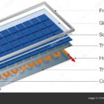
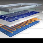
If you are building a solar powered system around this inverter, make sure your solar array and charge controller can replenish the battery bank. Understanding how solar panels generate electricity and the main components of a solar panel will help you size everything correctly. For a full overview, check our guide on the various panel technologies available today.
Stay safe. Measure twice. Wire once.

Similar Posts