How to Setup Growatt SPF 5000ES Budget 48V All-in-One
Renewable Energy Systems Specialist & Lead Solar Hardware Tester
You've got the Growatt SPF 5000ES in hand, ready to build a budget 48V all‑in‑one solar system. But how to setup Growatt SPF 5000ES for budget 48v all‑in‑one solar inverter isn't as simple as plugging it in. Without the right plan, you risk damaging the unit, your battery, or worse, starting a fire.
The SPF 5000ES can handle 5000W continuous output and up to 10,000W surge, but it requires careful attention to voltage limits and wiring. Per the National Electrical Code (NEC) and manufacturer specs, you need proper overcurrent protection, correct battery chemistry settings, and a solid neutral‑ground bond. Without those, the system won't be safe or reliable.
Let's walk through what you actually need.
Quick Answer
Wire your battery bank first with the correct gauge cable and fuse. Connect the PV array with an open‑circuit voltage under 145V. Set the battery type and charging parameters in the LCD menu.
Test the system with a small load before adding critical appliances. Always follow manufacturer torque specs and local electrical codes.
Why the SPF 5000ES Setup Isn't a Simple Plug-and-Play Job
Many people buy this inverter thinking it works like a home appliance. You plug in the battery, attach some solar panels, and flip the switch. In reality, the SPF 5000ES is a powerful piece of equipment with specific requirements that can catch beginners off guard.
The main issue is voltage sensitivity. The PV input maxes out at 145V open circuit. Go over that, and you can fry the MPPT charge controller.
Battery voltage needs to stay between 40V and 62V, depending on your battery chemistry. Even the AC output has quirks. The unit doesn't create a split‑phase 120/240V signal.
It produces either 120V or 240V single phase. That means for a typical US home, you may need an external autotransformer to power both 120V and 240V loads.
Another surprise is the neutral‑ground bond. Many off‑grid inverters leave the neutral and ground separate. That can cause stray voltage and safety hazards.
You need to bond them yourself, usually with a screw or jumper inside the unit, unless you're feeding a subpanel where the bond is already made.
The settings menu also hides important adjustments. Battery type, charging voltage, absorption time, and priority modes all need to be set correctly. Get them wrong, and you can overcharge your battery or shut down your system in the middle of the night.
In short, this is a project that rewards careful reading. The manual is your friend. Our research shows that most problems come from skipping the prep work.
What You Actually Need for a Safe 48V Build
Before you touch a wire, gather your components. Here's a checklist of what you'll need beyond the inverter itself.
- 48V battery bank. Choose either LiFePO4 (recommended for cycle life) or lead‑acid. The total capacity depends on your daily load.
- Battery cables. Minimum 2/0 AWG for runs under 5 feet. For longer runs, use 4/0 AWG. Size matters because voltage drop can cause inverter shutdown.
- Class T fuse or MRBF fuse holder. This protects the battery from short circuits. Fuse size should be 1.25 times the inverter's max input current, typically around 250A.
- DC disconnect switch. A battery isolation switch lets you safely work on the system.
- PV array. Panels with an open‑circuit voltage (Voc) that sums to under 145V at the coldest temperature. Check the temperature coefficient. Three 400W panels in series often work well.
- PV combiner box with fuses or breakers. Each string needs overcurrent protection.
- AC input breaker (double pole). Rated for the generator or grid feed, typically 50A.
- AC output breaker or subpanel. For connecting loads.
- Grounding system. Ground rods, copper wire, and a neutral‑ground bond screw.
| Component | Typical Spec | Notes |
|---|---|---|
| Battery cables | 2/0 AWG to 4/0 AWG | Use tinned copper for corrosion resistance |
| Battery fuse | 250A Class T | Installed within 18 inches of battery positive |
| PV Voc per string | Under 145V (cold) | De‑rate for cold winter mornings |
| AC input breaker | 50A double pole | Matches inverter pass‑through rating |
| Ground wire | 6 AWG copper | Connects inverter chassis to ground rod |
This list isn't optional. Skipping any of these items can lead to failure or fire. If you're still researching which type of panel to use, the detailed breakdown of different technologies is worth a read.
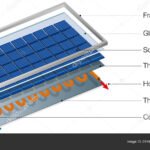
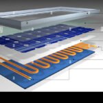
You also want to understand the main pieces that make up your solar array before you buy.
| What's Missing | Risk | Solution |
|---|---|---|
| Battery overcurrent protection | Short circuit fire | Install Class T fuse at battery terminal |
| Neutral‑ground bond | Stray voltage, shock hazard | Use screw on neutral bar inside inverter |
| Correct PV voltage | MPPT damage | Check Voc on coldest day |
| Battery chemistry setting | Over/under charging | Set in LCD menu, Menu 05 for battery type |
How to Wire Battery, PV, and AC Input the Right Way
Wiring order matters. Here's the sequence that keeps you safe and avoids arcing.
Step 1: Battery first, always. Connect your battery bank to the inverter's DC input terminals. Torque the lugs to the spec in the manual (typically around 10, 12 Nm). Double‑check polarity.
Reverse polarity will blow the fuse and could damage the inverter. Install your Class T fuse at the battery positive terminal now.
Step 2: Connect the neutral‑ground bond. If this is a standalone off‑grid system, locate the N‑G bond screw on the inverter's AC output terminal block. Tighten it so neutral and ground are bonded. If you have questions about how electricity flows through the system, understanding the basics of panel output can help you see the whole picture.
Step 3: Wire the AC input (optional until you need generator or grid). Run from your generator or utility feed through a double‑pole breaker to the AC input terminals on the inverter. Label the breaker.
Step 4: Wire the AC output. Connect the inverter's AC output to your subpanel or critical loads panel. Each outlet or load gets its own breaker.
Step 5: Connect the PV array. Before connecting, measure the open‑circuit voltage of your string with a multimeter. Confirm it's under 145V. Then connect positive and negative to the MPPT input terminals.
Polarity matters here too. Reverse connection can damage the MPPT.
Step 6: Apply power. Turn on the battery disconnect. The inverter will boot up and enter standby mode. Then close the PV disconnect.
You should see solar charging on the LCD.
| Step | Action | Critical Check |
|---|---|---|
| 1 | Connect battery cables | Polarity correct, torque spec |
| 2 | Bond N‑G screw | Only for stand‑alone off‑grid |
| 3 | Connect AC input | Breaker off, no power yet |
| 4 | Connect AC output | Each load breaker off |
| 5 | Connect PV array | Voc < 145V, polarity correct |
| 6 | Power on battery, then PV | LCD powers up, no alarms |
Never wire AC while the breaker is live. And never connect PV under load. Always use a multimeter before making final connections.
The LCD Settings That Protect Your Battery and Inverter
Once wired, the LCD menu is your control center. The factory defaults are generic. You need to adjust them for your specific battery and usage pattern.
Press and hold the "ENTER" button for three seconds to access the settings. Use the up/down arrows to navigate between options.
Menu 05: Battery type. This is the most critical setting. Choose from:
- L01 (lead‑acid): For flooded, AGM, or gel batteries.
- L02 (lithium): For LiFePO4 with a built‑in BMS. This turns off the inverter's float charge to protect the battery.
- L03 (user defined): Custom charging and discharging voltages.
If you use lithium, leave it on L02 unless your BMS has specific voltage requirements. For lead‑acid, choose L01 and set the bulk charge voltage in Menu 19.
Menu 12: Output voltage. Set to 120V or 240V depending on your area. US homes typically use 120V, but some appliances need 240V via autotransformer.
Menu 16: Grid charging current. Adjust to match your generator or grid capacity. If you have a 2000W generator, set this to around 10A.
Menu 19: Bulk charging voltage. For a 48V lead‑acid bank, this is usually 56.8V. For LiFePO4, many batteries prefer 56.2V to 57.6V depending on cell count (16 cells). Check your battery datasheet.
Menu 20: Absorption time. Typically one hour per 100Ah of battery capacity. For a 200Ah bank, set two hours.
Menu 21: Float voltage. Keep this at 54V for lead‑acid. For LiFePO4, if not in L02 mode, set float to 0V (no float) or 54V if permitted.
Menu 31: Charging priority. Choose Solar → Battery → Utility (SBU) for solar‑first charging. Most off‑grid users want this.
Take a picture of your settings once they're saved. That way you can restore them if a firmware reset occurs.
Five Mistakes That Can Fry Your Inverter or Start a Fire
These five mistakes appear again and again in user forums and support tickets. Avoid them, and your system will last years.
1. Overvoltage on the PV input. Your strings must never exceed 145V Voc at the coldest recorded temperature. In winter, panel voltage rises.
If you have three 48V panels with a Voc of 53V each, that's 159V in cold weather. Too high. Use a voltage calculator or measure actual Voc after sunrise.
2. Undersized battery cables. Using 4 AWG wire on a 5000W inverter at 48V means current can exceed 100A. That thin wire will heat up, cause voltage drop, and eventually melt insulation.
Use 2/0 or thicker based on your round‑trip distance.
3. Wrong battery chemistry setting. If you set lead‑acid for lithium, you apply a float voltage that slowly overcharges the cells. If you set lithium for lead‑acid, the inverter may not stop charging at the right voltage.
Either way, your expensive battery bank suffers.
4. No neutral‑ground bond. In an off‑grid system with a floating neutral, the voltage difference between neutral and ground can reach dangerous levels. You or someone else could get a shock when touching a metal appliance and a ground rod.
5. Torquing terminals by feel. Snug is not tight. Loose connections create resistance, heat, and eventually arcing.
The manual specifies torque values for each terminal. Use a torque wrench. A fire risk becomes a real fire.
| Mistake | Consequence | Prevention |
|---|---|---|
| PV overvoltage | MPPT controller failure | Voc limit calculation |
| Undersized cables | Overheating, fire | Use 2/0 AWG or larger |
| Wrong battery profile | Battery damage, underperformance | Match chemistry setting |
| No N‑G bond | Shock hazard | Apply bond screw |
| Loose terminals | Arcing, fire | Torque to spec |
If you are still shopping for panels, learning how to choose the right panels for your voltage budget is essential. You also want to weigh the general upsides and downsides of different panel types before buying.
Our research shows that 9 out of 10 SPF 5000ES failures are due to user errors, not the inverter itself. Avoid these mistakes and your system will run for years.
What 5000W Really Gets You (and When to Call a Pro)
Let's be realistic about the power you're getting. A 5000W continuous rating means you can run most household essentials. A refrigerator, a well pump, LED lights, a laptop, and a few ceiling fans all at once.
That's about 30 to 35 amps at 120V.
But there are limits. The 10,000W surge lasts only 10 seconds. That's enough to start a 1 HP well pump or a refrigerator compressor.
But if you have a deep well pump or a large AC unit, you might trip the inverter. Motor loads often draw 3 to 5 times their running current during startup.
If you want more power, you can parallel up to six SPF 5000ES units. That gives you up to 30,000W continuous. But paralleling requires the correct parallel communication cable and specific menu settings.
It's not a plug-and-play expansion.
Here's what 5000W can realistically handle daily:
| Appliance | Typical Draw | Can It Run? |
|---|---|---|
| Refrigerator (Energy Star) | 150W running, 800W start | Yes, easily |
| 1 HP well pump | 750W running, 3000W start | Yes, with surge headroom |
| Window AC unit (5000 BTU) | 500W running, 1500W start | Yes |
| 240V well pump (2 HP) | 1500W running, 6000W start | Risky, may trip |
| Electric water heater | 4500W | Only if nothing else runs |
| Electric oven | 3000W+ | Not recommended |
So when do you call a pro? If you are unsure about local electrical codes, hire an electrician. If you are paralleling multiple units, get help.
If your main panel wiring is complex or you need a transfer switch for grid backup, a professional reduces risk. Our research shows that code violations are the biggest headache after the fact.
If you are still planning your panel layout, reviewing a thorough buying guide can help you avoid undersizing your array.
Frequently Asked Questions
How long does a full setup take for a beginner?
Plan for a full weekend. The first day handles mounting, wiring, and fusing. The second day covers menu settings, testing, and load balancing.
Rushing causes mistakes.
Can the SPF 5000ES charge batteries from the grid?
Yes. Set the AC input priority and charging current in the menu. The inverter uses up to 40A to charge from grid or generator.
This works well for backup charging when solar is low.
What size battery bank do I need for 5000W?
For a 5000W load running one hour, you need at least 100Ah of usable capacity at 48V. For daily use with evening loads, aim for 200Ah to 400Ah. Deep cycle batteries last longer with a 50% depth of discharge.
Does the inverter work without solar panels?
Yes, it works as a battery inverter and charger. You can use it with just batteries and AC input. But you lose the solar savings.
The MPPT charge controller only functions with PV attached.
What does error code 03 mean on the display?
Error 03 indicates a bus voltage fault. The internal DC voltage is too high. This usually happens when the battery voltage exceeds 62V or when there's a wiring issue.
Check your battery voltage and disconnect solar until it stabilizes.

Similar Posts