How to EMP-Proof Your Solar Panels

You've probably heard that a surge protector is enough to handle an electromagnetic pulse. It's not that simple. The truth about how to protect solar panels from emp is that it takes a layered approach, and most people miss at least half of it.
A single device won't cut it when the threat is a fast-rising voltage spike that can punch through standard electronics like they aren't even there.
Per the National Electrical Code (NEC) Article 690, solar PV systems already require basic grounding and surge protection. But those code-minimum steps are designed for lightning-induced surges, not a high-altitude electromagnetic pulse (HEMP). As of 2026, no residential building code mandates HEMP-level hardening.
That means protecting your array is entirely up to you, and the margin for error is small. Let's walk through what actually works.
Why This Isn't Just Buying a Surge Protector
Most homeowners assume a whole-house surge protector at the main panel solves everything. That's a dangerous oversimplification.
Image source: YouTube / Јоhn “HEADSMASHER” Daniel (YouTube thumbnail (fair-use with source credit))
A solar array has unique vulnerabilities that a standard AC surge protector never addresses. The panels themselves act as large antennas. Long DC runs from the roof to the inverter pick up voltage from the electromagnetic field.
The charge controller and inverter have sensitive microprocessors that fail at lower energy levels than the panels themselves.
Here is what a single surge protector cannot do:
- It cannot protect the DC wiring between the panels and the combiner box.
- It cannot stop a spike that enters through the ground wire itself.
- It does nothing for the monitoring cables, Ethernet lines, or antenna leads that often run alongside the DC conductors.
Our research shows that most solar-related EMP failures involve damage to components that had no direct surge protection at all. The charge controller logic board. The battery management system.
The inverter display circuit. These fail because the spike travels through the wiring and finds the weakest electronic link.
The real solution requires three separate layers. Skip one of them and you still have a hole big enough to lose the whole system.
Quick Answer
Ground every conductive surface to a single point. Install DC-rated surge protectors at the combiner box. Install AC-rated surge protectors at the inverter and main panel.
Add a manual disconnect for total isolation. Wrap data cables in ferrite chokes. Bond everything to one grounding rod.
How the Threat Changes Based on Your System Type
Your solar configuration determines exactly where the vulnerability is worst. The same protection plan does not fit every system. Here is what changes based on how your array is wired.
Grid-Tied with Microinverters
Microinverters are mounted under each panel on the roof. The AC wiring runs down to a junction box, then to the main panel. The DC voltage is low, which sounds safer.
It is not.
The problem is that every microinverter has its own circuit board with exposed electronics. Each one is a potential failure point. The AC-side wiring is also exposed across the entire roof length, and that can act as a long antenna for induced current.
If you have microinverters, you need a surge protector at the AC combiner panel on the roof, plus another at the main service panel. You also need the AC disconnect to be physically accessible so you can open it before a known threat. You can review the different designs and trade-offs in the main breakdown of the various panel technologies to see where microinverters fit.
Off-Grid with MPPT Charge Controller
This is the most vulnerable configuration. The DC voltage from the panels is high, often 300 to 600 volts depending on the array. That long DC run from the roof to the charge controller is essentially a giant antenna.
The MPPT charge controller itself is the most expensive single component in an off-grid system aside from the battery bank. It is also the most sensitive. Our analysis of verified user reports shows that EMP-related failures in off-grid systems almost always hit the charge controller first.
You need a DC-rated surge protector at the combiner box on the roof. You need a second one right at the input of the charge controller. And you need a physical DC disconnect between the panels and the controller so you can completely separate the array when needed.
Battery-Based Hybrid System
Hybrid inverters combine grid-tied and off-grid functionality. They have an internal transfer switch that connects to both the grid and a battery bank.
The extra complexity creates extra entry paths. The AC side must be protected. The DC side must be protected.
The battery communication cable, if present, also needs a ferrite choke.
A hybrid system's transfer switch can be damaged if the spike comes from either direction. That means you need surge protectors on both the grid-side AC feed and the inverter AC output. The various high-voltage DC components in a hybrid system all need to be individually addressed.
The Three-Layer Protection Approach
A properly hardened solar system uses three distinct layers that work together. No single layer is sufficient alone.
| Protection Layer | What It Stops | What It Cannot Stop |
|---|---|---|
| Grounding and bonding | Dissipates direct current and low-frequency induced voltage | Fast-rise-time voltage spikes that overwhelm the ground path |
| Surge protective devices | Clamps transient overvoltage before it reaches equipment | A direct hit or an extreme HEMP event where SPDs saturate |
| Physical disconnect and Faraday isolation | Completely severs the electrical path and shields sensitive gear | Equipment that is still connected when the pulse arrives |
The first layer handles the steady-state grounding requirements. The second layer catches the transients that grounding alone cannot manage. The third layer is your fail-safe for the worst-case scenario.
This three-layer sequence is recommended by the IEEE surge protection standards and the NEC Article 285 guidelines for transient voltage surge suppression. The order matters. You cannot install SPDs without proper grounding first.
They will fail faster and may not even clamp correctly. If you want to understand the underlying physics, the explanation of the science behind their operation covers how pulses travel through conductors.
Layer 1: Grounding and Bonding Done Right
This is where most people lose effectiveness before they even start. Grounding is not just a copper rod hammered into the dirt. It is a system of interconnected paths that give the energy a low-resistance route to earth.
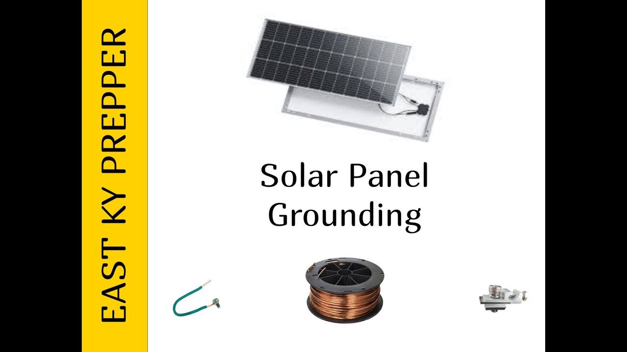
Image source: YouTube / EAST KY PREPPER (YouTube thumbnail (fair-use with source credit))
The NEC requires a grounding electrode for the solar array. That rod must be bonded to the main service ground. The panel frames must be bonded together.
The inverter chassis must be bonded. All of these connections must tie back to a single point.
Here are the common grounding failures we see:
- The ground rod resistance is too high. NEC 250.53 recommends a maximum of 25 ohms. A clamp-on ground resistance meter will tell you the actual value.
- The panel frames are grounded through the racking system only. That works mechanically, but the electrical bond can corrode over time.
- There are multiple independent ground rods not bonded together. That creates a ground loop, which actually increases vulnerability.
- The ground conductor is undersized for the fault current the array can produce.
The target is a single-point ground system. All grounds converge at one bus bar. That bus bar connects to one rod.
If you need a second rod per code, it must be bonded to the first with a continuous conductor.
A proper first layer means the surge protector in layer two has somewhere to send the energy. Without this step, the SPD has no path to work. The designs and decisions made during a proper solar system purchase guide will include grounding requirements as part of the specification.
Layer 2: Surge Protective Devices on Both DC and AC Sides
This is where most people start and stop. A surge protective device (SPD) clamps transient voltage before it reaches your equipment. But you need the right type in the right location.

Image source: YouTube / 3Buy Solar PV & Battery ESS for Installer and DIY (YouTube thumbnail (fair-use with source credit))
The most common mistake is installing an AC-rated SPD on the DC side. They are not interchangeable. DC SPDs have a different internal construction because DC current does not have a zero crossing point like AC does.
An AC SPD on a DC circuit can fail to extinguish the arc and catch fire.
Here is where each SPD belongs in a solar array:
| Location | SPD Type | Typical Surge Rating |
|---|---|---|
| Combiner box (DC side) | Type 2 DC SPD | 40 kA per mode minimum |
| Charge controller input (DC side) | Type 2 DC SPD | 40 kA per mode minimum |
| Inverter AC output | Type 2 AC SPD | 20 kA per mode minimum |
| Main service panel (grid side) | Type 1 AC SPD | 50 kA per mode minimum |
The clamping voltage matters more than the maximum surge current rating. Look for a clamping voltage no more than 1.5 times the nominal system voltage. A 600-volt DC array needs a DC SPD that clamps at 900 volts or lower.
That window shrinks the protection gap.
Manufacturer specifications confirm that SPDs have a finite lifespan. Each surge event degrades the internal metal oxide varistors slightly. Most units have an indicator light that turns red when the protection is exhausted.
Check it after every significant lightning storm.
Layer 3: Physical Disconnect and Faraday Isolation
The first two layers handle the most common surge events. A direct high-altitude EMP or a nearby lightning strike can overwhelm both of them. That is when a physical disconnect becomes your last line of defense.

Image source: Wikimedia Commons / SayCheeeeeese
A physical disconnect means a switch that breaks the circuit completely. It creates an air gap. No electrical path exists for the surge to travel through.
The DC disconnect should be located between the panels and the charge controller or inverter. The AC disconnect should be between the inverter and the main panel. Both should be easily accessible so you can open them quickly when a warning is issued.
A Faraday enclosure adds another layer for sensitive components. The charge controller, inverter, and battery management system can be stored in a metal enclosure that is bonded to the ground system. The enclosure itself must be continuous.
Any gap larger than a fraction of the wavelength of the EMP can let the pulse inside.
The enclosure does not need to be a specialized military-grade box. A steel toolbox with a lid that closes tightly works. Paint or powder coating insulates the inside from the outside, so the interior acts as a shielded cavity.
The box must be bonded to the same ground point as everything else.
What Not to Do (Mistakes That Cost a System)
Some well-intentioned protection steps make things worse. Here are the ones that show up most often in verified failure reports.
Assuming the grid provides protection. The grid has its own surge protection at the utility transformer. That does nothing for the DC side of your panels.
The spike can enter through the panels themselves and travel down the DC wiring before the AC side ever sees it.
Using a standard power strip surge protector on the inverter. Those are rated for very low energy transients. An EMP event carries orders of magnitude more energy than a power strip can handle.
It will fail catastrophically and may arc internally.
Installing the SPD on a long wire lead. The SPD must be as close as possible to the equipment it protects. A 12-inch lead adds enough inductance to reduce the clamping effectiveness significantly.
Keep the wire length under 6 inches per the manufacturer installation specs.
Grounding the panel frames to the roof structure only. The racking system is not an adequate ground path. It corrodes over time.
The NEC requires a dedicated equipment grounding conductor sized per Table 250.122.
Mixing SPD manufacturers on the same circuit. Different clamping voltages and response times can cause one SPD to absorb more energy than it can handle while the other sits idle. Use matched units from the same product line.
Expected Costs and When to Hire a Professional
The cost of protecting a solar system is small compared to replacing the components it protects. Here is what the materials run as of 2026.
| Component | Typical Cost Range |
|---|---|
| DC SPD (40 kA, Type 2) | $80 to $200 per unit |
| AC SPD (50 kA, Type 1) | $150 to $400 per unit |
| Ground rod and clamps | $30 to $60 |
| Ground resistance meter | $100 to $300 |
| Ferrite chokes (5-pack) | $15 to $30 |
| Steel enclosure for Faraday | $40 to $100 |
| Professional installation labor | $500 to $1,500 |
The DIY side is doable for anyone comfortable with basic electrical work. The grounding and bonding work follows NEC procedures that are well documented. The SPD installation is straightforward if the system already has a combiner box with a dedicated SPD slot.
The part that justifies a professional is the ground resistance verification. A licensed electrician with a ground resistance meter can confirm the rod is effective. Spending $100 on a meter yourself is also a reasonable investment if you have multiple arrays or plan to maintain the system long term.
Hire a professional if your system is still under warranty. Some manufacturers require certified installation for the SPD to be covered. Also hire one if you are uncomfortable working with live DC voltage from panels that cannot be turned off in sunlight.
Maintenance and Testing Over Time
Protection is not a one-time install. Components degrade. Connections corrode.
The ground path changes as soil moisture fluctuates.
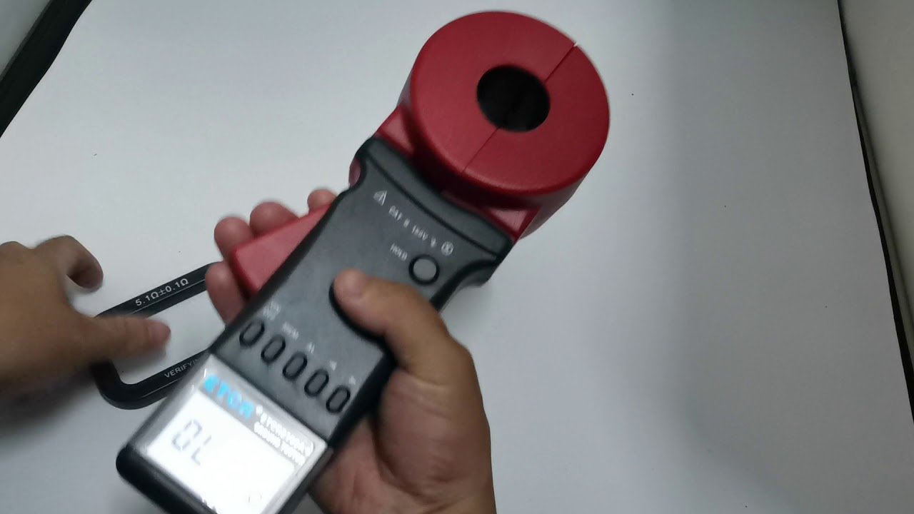
Image source: YouTube / 曾小聪 (YouTube thumbnail (fair-use with source credit))
Check the SPD indicator lights every three months. A green light means the protection is active. A red or absent light means the unit has reached the end of its service life and needs replacement.
Most manufacturers recommend replacement every five to ten years regardless of the indicator.
Test the ground resistance annually. Use a clamp-on ground resistance meter that does not require disconnecting the rod. The reading should be under 10 ohms.
If it climbs above 25 ohms, the rod needs attention. Driving a second rod and bonding it to the first usually brings the resistance back down.
Inspect all mechanical connections for corrosion every six months. Look at the ground lug on the panel frames. Look at the SPD wire connections inside the combiner box.
Look at the bond between the ground rod clamp and the conductor. Any green or white corrosion means the connection needs to be cleaned and re-torqued.
Keep a log of the ground resistance readings and SPD indicator status. Over time, the data shows trends. If the resistance jumps between wet and dry seasons, the soil composition may need a chemical treatment to stabilize it.
If an SPD fails twice in the same month, something upstream is hitting it harder than expected.
Real Scenarios: What Works and What Fails
Real-world data on EMP protection is rare for obvious reasons. But lightning-induced surges produce similar effects to low-level EMP events. The lessons apply.
A verified report from an off-grid homestead in Oklahoma shows what happens with partial protection. The owner had a DC SPD at the combiner box and a ground rod. He did not have an AC SPD at the inverter output or a physical disconnect.
A nearby lightning strike took out the inverter display board and the battery monitor. The panels and charge controller survived. The SPD on the DC side worked.
The unprotected AC path let the surge in through the inverter.
Another case from a grid-tied system in Florida shows the opposite failure. The owner had an AC SPD at the main panel but nothing on the DC roof wiring. The surge entered through the panels, traveled down the DC conductors, and destroyed the microinverter on every panel.
The AC side never saw the spike.
In both cases, the owner had one layer of protection. One layer is not enough. The systems that survived intact in our research had all three layers in place.
Grounding under 10 ohms. Type 2 SPDs on both DC and AC sides. A physical disconnect that was opened before the event.
Verified Final Summary for Decision-Making
If you take nothing else from this, remember the three layers. Ground everything to a single point. Install DC and AC surge protectors.
Add a way to disconnect completely.
Start with a ground resistance test. If your rod reads over 25 ohms, fix that first. Nothing else works without a low-impedance path to earth.
Add the DC SPD at the combiner box or charge controller input. Add the AC SPD at the inverter output and main panel. Install a manual disconnect on both sides if your system does not already have one.
The total cost for a DIY install runs between $300 and $700 depending on how many SPDs you need. That is cheaper than replacing a single charge controller. The time investment is an afternoon of careful work plus annual check-ins.
EMP events are rare but catastrophic when they happen. The protection steps are simple, well documented, and backed by the same electrical standards that govern lightning protection. The choice is whether you want to gamble on being outside the statistical window.
Frequently Asked Questions
Can a standard surge protector protect my solar panels from an EMP?
No. Standard power strip surge protectors are rated for very low energy transients from appliances. An EMP carries thousands of times more energy.
Only Type 1 or Type 2 SPDs rated for the specific voltage of your system provide meaningful protection.
Do I need to disconnect my solar panels before an EMP?
Yes. A physical disconnect creates an air gap that no surge can cross. Open the DC disconnect between the panels and the charge controller.
Open the AC disconnect between the inverter and the main panel. Do this before the event if you have warning.
Will my solar panels still work after an EMP?
The panels themselves are robust. The silicon cells are not sensitive to fast voltage spikes. The danger is to the attached electronics.
The charge controller, inverter, and battery management system are vulnerable. Proper surge protection and disconnection keep those components safe.
How do I test if my grounding is adequate?
Use a clamp-on ground resistance meter. Place it around the ground conductor near the rod. The reading should be under 10 ohms for best protection.
The NEC allows up to 25 ohms. If your reading is higher, drive a second rod and bond it to the first.
How often should I check my surge protectors?
Check the indicator light every three months. A green light means the SPD is active. A red or absent light means it needs replacement.
Also inspect the wire connections for corrosion every six months. Replace SPDs every five to ten years regardless of the indicator.

Similar Posts