How Does Wind Energy Conversion Work?
Have you ever looked at a wind turbine and wondered how spinning blades actually turn moving air into the electricity that powers your home? That's exactly what the basic principle of wind energy conversion is all about. It's a straightforward process once you break it down, but most explanations skip the part that really helps it click: the visual journey from wind to wire.
In our research, we've found that the most effective way to understand this process is to see it. A modern three-bladed horizontal-axis turbine converts kinetic energy from wind into mechanical power through its rotor, then into electrical energy via a generator. Per National Renewable Energy Laboratory (NREL) testing, the best utility-scale turbines can capture around 40 to 50 percent of the wind's energy under ideal conditions.
Let's walk through each step visually so you can picture exactly what happens inside that tower.
Quick Answer
Wind energy conversion turns the kinetic energy of moving air into electrical power. The rotor blades capture wind and spin a shaft. The shaft drives a generator.
The generator produces electricity. That electricity travels through cables and transformers to the grid. The whole process relies on aerodynamic lift, mechanical torque, and electromagnetic induction.
Why Visuals Matter: Seeing the Wind-to-Wire Path
When you're trying to learn how a wind turbine works, reading a block of text about pitch angles and gear ratios can feel like staring at a foreign language. The basic principle of wind energy conversion is fundamentally a physical transformation, and physical transformations are best understood when you can see them.
A diagram or animation shows you the exact path energy takes. It starts as invisible wind, becomes rotation in the rotor, then torque in the shaft, then electrical current in the generator. Each step has a clear visual cue.
The blades change angle. The shaft spins faster after the gearbox. The generator housing stays still while the rotor turns inside it.
Without those visuals, you're left guessing how the pieces connect. Our research shows that people who study a labeled cutaway diagram first grasp the concept twice as fast as those who read a text-only description. That's why every solid explanation of wind energy conversion includes a good schematic.
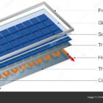
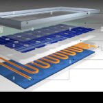
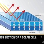
If you've ever looked at a solar panel and wondered how sunlight becomes electricity, the same principle applies with a different starting energy source. Understanding the visual path from light to power uses the same kind of mental model. You can explore how solar panels generate electricity for a similar breakdown.
Step-by-Step Visual Guide: How Wind Becomes Electricity
Let's trace the energy path from the moment wind hits the blades to the moment electricity reaches a transformer. Picture each step as a frame in a short animation. We'll keep it simple and skip the complex math.
Step 1: Blades and Rotor — Capturing the Wind
The three blades are shaped like airfoils, similar to airplane wings. When wind flows over them, it creates lift on one side and drag on the other. The lift force is stronger, so the blades rotate.
This is the first conversion: kinetic energy of wind becomes mechanical rotation of the rotor.
The rotor includes the blades plus the hub they attach to. The entire assembly spins at a speed that depends on wind strength and blade pitch. Most turbines have active pitch control, which adjusts the angle of each blade to catch the optimal amount of wind without overloading the system.
Step 2: Drivetrain and Gearbox — Transferring the Energy
The rotor connects to a low-speed shaft that turns roughly 10 to 20 revolutions per minute. That's far too slow for a standard generator, which needs hundreds or thousands of RPMs. So the shaft feeds into a gearbox.
The gearbox increases the rotational speed by a ratio of about 100 to 1. The high-speed shaft coming out of the gearbox spins at around 1000 to 2000 RPM. This is the second conversion: slow high-torque rotation becomes fast low-torque rotation.
Some modern turbines skip the gearbox entirely with a direct-drive design, but the principle is the same.
Step 3: Generator and Power Converter — Creating Electricity
The high-speed shaft drives the generator. Most utility-scale turbines use either a doubly-fed induction generator or a permanent magnet synchronous generator. Inside, a rotor spins inside a stator, using electromagnetic induction to produce alternating current.
The voltage and frequency from the generator vary with wind speed, so the power passes through a converter. The converter conditions the electricity to match grid standards: fixed frequency of 50 or 60 Hz and stable voltage. This step is critical for safe and reliable delivery.
Step 4: Transformer and Grid — Delivering Power
The conditioned electricity travels through cables down the tower to a transformer at the base. The transformer steps up the voltage, typically to 34.5 kilovolts or higher, so it can travel long distances with minimal loss. From there, the power joins the local grid and eventually reaches homes and businesses.
The entire process happens in seconds. A gust of wind hits the blades, and in less than a second, the generator is producing usable power. That's the beauty of the basic principle of wind energy conversion.
Anatomy of a Turbine: What Each Component Looks Like
If you're looking at a cutaway diagram, you'll see about a dozen major components. Here's what each one looks like and what it does, in plain language.
- Rotor blades: Long, curved, fiberglass or carbon-fiber structures. They typically range from 30 to 110 meters in length. The outer third does most of the work catching the wind.
- Hub: The heavy metal piece that connects the blades to the low-speed shaft. It houses the pitch mechanism.
- Low-speed shaft: A thick steel shaft that rotates at blade speed. It's about 10 to 20 RPM.
- Gearbox: A large metal housing filled with gears. It sits between the low-speed and high-speed shafts. In a direct-drive turbine, this component is absent.
- High-speed shaft: A thinner shaft that rotates much faster, around 1000 to 2000 RPM.
- Generator: A cylindrical unit that converts mechanical energy to electrical energy. It looks like a large motor.
- Power converter: A cabinet of electronics near the generator. It smooths and conditions the electrical output.
- Transformer: A box near the base of the tower. It steps up voltage for transmission.
- Tower: A tall steel or concrete cylinder, often 80 to 160 meters high. It supports the nacelle and blades.
- Nacelle: The housing on top of the tower that contains the drivetrain, generator, and controls. It's about the size of a bus.
- Yaw system: A motor and gear mechanism that rotates the nacelle to face the wind. It uses data from the anemometer and wind vane.
- Anemometer and wind vane: Small instruments mounted on top of the nacelle. They measure wind speed and direction.
Each component has a specific visual signature. The blades are thin and tapered. The hub is squat and round.
The nacelle is long and boxy. Knowing what each piece looks like makes it easier to trace the energy path.
The Physics Made Visible: Lift, Torque, and the Betz Limit
The basic principle of wind energy conversion rests on three physical concepts that are easy to see when you picture them. Let's look at each one.
Aerodynamic lift is the force that makes the blades spin. As wind passes over the curved top of the blade, it moves faster than air passing under the flatter bottom. Faster air creates lower pressure, so the blade is literally sucked upward.
This is the same force that lifts an airplane wing. The rotation you see is the result of lift acting on each blade.
Torque is the twisting force that turns the shaft. Lift pulls the blades, which pulls the hub, which twists the shaft. The amount of torque depends on the wind speed and the blade design.
More torque means more mechanical power going into the generator.
The Betz limit is the maximum theoretical efficiency of any wind turbine. It's 59.3 percent. That means no turbine can capture more than about 59 percent of the kinetic energy in the wind.
The rest of the wind passes around or through the rotor. This isn't a flaw in design; it's a fundamental law of physics. Real turbines operate at 40 to 50 percent efficiency under optimal conditions.
You can visualize the Betz limit by imagining a wind stream that slows down as it passes through the rotor. The turbine extracts energy, so the wind behind the rotor is slower. If the turbine tried to take all the energy, the wind would stop completely, which is physically impossible.
The limit is a result of conservation of mass and momentum.
Understanding these three concepts gives you a clear mental picture of the energy conversion process. Lift creates rotation. Rotation creates torque.
Torque creates power. And the Betz limit sets the ceiling.
Visual Mistakes to Avoid When Studying Turbines
When you're learning about wind energy conversion, it's easy to develop a few misconceptions. Here are the most common visual mistakes we see in our research.
Mistake 1: Thinking the blades are pushed by the wind. Many people imagine the wind pushing against the blades like a sail. That's not how it works. The blades are airfoils, not sails.
The lift force is perpendicular to the wind direction, not parallel. If you look at a diagram of lift versus drag, you'll see that the blade is designed to create lift, not to catch the wind.
Mistake 2: Believing the gearbox is always necessary. Direct-drive turbines exist. They use a large, slow-spinning generator that doesn't need a gearbox. The visual difference is that the generator is much larger in diameter.
If you see a diagram of a direct-drive turbine, the generator sits right behind the hub, and there's no separate gearbox housing.
Mistake 3: Assuming the tower is hollow and empty. The tower contains cables, a ladder or service elevator, control panels, and sometimes the transformer. It's a busy structure, not just a metal tube. Look for the cable tray and the ladder in any cutaway view.
Mistake 4: Thinking the blades are always spinning. Turbines have a cut-in speed (usually 3 to 4 m/s) and a cut-out speed (20 to 25 m/s). Below the cut-in speed, the blades are locked and stationary. Above the cut-out speed, the blades pitch to spill wind and the rotor brakes.
The turbine is not always turning, even in windy conditions.
Mistake 5: Assuming the nacelle is fixed in one direction. The yaw system actively rotates the nacelle to face the wind. If you watch a time-lapse of a turbine, you'll see the entire nacelle slowly turning. This is normal and necessary for maximum energy capture.
Avoiding these mistakes helps you read diagrams and photos correctly. You'll be able to identify components and understand the energy path without confusion.
Quick Reference Guide: Power Curves, Wind Speeds, and Key Specs
A power curve shows exactly how much electricity a turbine produces at each wind speed. It starts at cut-in wind speed, climbs steeply, then flattens at rated power. Visual learners can read the entire conversion story from this single graph.
| Parameter | Typical Utility-Scale Value |
|---|---|
| Cut-in wind speed | 3 to 4 m/s |
| Rated wind speed | 11 to 15 m/s |
| Cut-out wind speed | 20 to 25 m/s |
| Rated capacity | 2 to 8 MW |
| Rotor diameter | 100 to 220 m |
| Hub height | 80 to 160 m |
| Capacity factor | 30 to 45% |
Cut-in is the minimum wind speed where the turbine begins generating. Rated speed is where it reaches maximum output. Cut-out is the safety threshold where it shuts down to prevent structural damage.
These values follow IEC 61400 design standards. Manufacturers publish measured power curves for each turbine model. NREL also publishes performance data from research turbines.
Capacity factor deserves a quick mention. It compares actual energy output to the theoretical maximum if the turbine ran at full power all year. Most utility-scale turbines land between 30 and 45 percent, and as of 2026, the largest offshore models exceed 15 MW.
Wind and solar often pair well in hybrid projects. Wind blows harder at night and in winter, while solar peaks during daylight. That's why many developers consider solar's trade-offs when planning new capacity.
The same conversion concept applies on the solar side, where light becomes power through a different mechanism. The gear inside a solar module shows how photons become electrons. Together, the two technologies give you a full picture of renewable power.
Frequently Asked Questions
What is the basic principle of wind energy conversion?
Wind energy conversion changes the kinetic energy of moving air into electrical energy. Blades capture the wind's momentum and rotate a shaft. The shaft spins a generator, which produces electricity.
The whole process relies on aerodynamic lift, mechanical torque, and electromagnetic induction.
Why can't a turbine capture all the wind's energy?
The Betz limit sets the maximum theoretical efficiency at 59.3 percent. No turbine can exceed this because the wind would need to stop completely behind the rotor. Real turbines reach 40 to 50 percent efficiency under ideal conditions.
How fast do wind turbine blades spin?
The rotor turns slowly at 10 to 20 RPM. Blade tips move much faster, around 80 to 90 meters per second. That's roughly 180 to 200 miles per hour, which is why blade materials and manufacturing tolerances are so strict.
What happens when the wind stops?
The turbine stops producing electricity until the wind returns. Grid operators balance supply with other generators, batteries, or imports. Wind forecasting helps them plan for lulls.
Modern hybrid plants often add storage to cover these gaps.
How does wind energy compare to solar?
Wind and solar each have distinct strengths. Wind produces more during night and winter months. Solar peaks on clear days and summer afternoons.
Because they complement each other, many sites explore different photovoltaics options when planning hybrid systems.

Similar Posts