Will a Solar Panel Survive an EMP?
If you've ever wondered will a solar panel survive an emp, you're not alone. It's one of the most common questions we hear from people building resilient energy systems. The short answer is more nuanced than a simple yes or no, it depends on a handful of specific conditions that you can control.
Modern solar panels contain semiconductor junctions and bypass diodes that respond to voltage surges in predictable ways. Per IEEE testing standards, a well-grounded, disconnected panel with intact bypass diodes can withstand induced currents far higher than what most consumer electronics can handle. The real challenge isn't the panel itself, it's everything connected to it.
Let's walk through exactly what happens and how to prepare.
Quick Answer
Will a solar panel survive an emp? It depends entirely on your setup. The silicon cells themselves are surprisingly tough. The real vulnerability lies in the connected electronics.
Protection comes down to grounding, surge protection, and isolation.
A bare panel sitting disconnected from any system has a very high chance of surviving. But once you add an inverter, a charge controller, or a battery management system, those components become the weak link. The panel's aluminum frame acts as a natural antenna, collecting induced energy and sending it straight into whatever is wired to it.
That's why your first question shouldn't be about the panel, it should be about the system.
How an EMP Actually Damages Electronics (The Three Phases)
Image source: YouTube / EIS Council (YouTube thumbnail (fair-use with source credit))
An electromagnetic pulse isn't one single event. It happens in three distinct phases, and each one affects your solar system differently. Understanding the difference is the key to knowing where your protection efforts should go.
E1 phase is the fastest and most intense. It arrives in nanoseconds and induces extremely high voltage spikes in any long wire or conductive surface. Solar panels are essentially large-area diodes mounted on aluminum frames, those frames and the long DC cables act as antennas for this pulse.
The energy hits the bypass diodes and the inverter's input stage first. If those components can't clamp the voltage quickly enough, they fail instantly.
E2 phase is slower and behaves more like a lightning strike. Your existing surge protection devices (SPDs) are designed for this type of event. If you have proper SPDs rated for DC solar circuits, you're reasonably well covered for E2.
The problem is that many solar installations only have AC-side surge protection, leaving the DC side exposed.
E3 phase is a low-frequency geomagnetic disturbance that lasts from seconds to minutes. It doesn't zap components instantly like E1 does. Instead, it saturates the iron cores in transformers, causing them to overheat and fail.
Large grid-tied solar farms with massive transformers are far more vulnerable here than a small residential system. But if your off-grid inverter uses a heavy copper transformer, E3 can still cause damage over time.
Here's a quick summary of how each phase hits your system:
| Phase | Speed | Primary Effect | Most Vulnerable Component |
|---|---|---|---|
| E1 | Nanoseconds | High-voltage spike | Bypass diodes, inverter input |
| E2 | Microseconds | Lightning-like surge | SPDs, charge controller |
| E3 | Seconds to minutes | Transformer saturation | Grid-tie inverter transformer |
The practical takeaway is this: E1 is the one that destroys electronics before you can blink. E2 you can protect against with standard gear. E3 mostly matters if you're running a large transformer.
For most homeowners with a modest solar setup, focusing on E1 protection gives you the biggest bang for your effort.
The Solar Panel Itself vs. The Rest of the System

Image source: Wikimedia Commons / Wikideas1
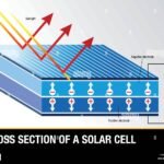
Here's the part that surprises most people: the actual solar panel is probably the most rugged component in your entire system. We're talking about a sandwich of tempered glass, silicon wafers, a polymer backsheet, and an aluminum frame. The silicon cells themselves are basically large-area diodes.
Diodes are inherently resistant to voltage spikes, they're designed to handle reverse bias and forward current. If you look at the different types of solar panels, you'll see that monocrystalline and polycrystalline cells share the same fundamental semiconductor structure, just arranged differently.
The weak points on the panel are the bypass diodes and the junction box. Bypass diodes are small semiconductor devices mounted inside the junction box on the back of the panel. Their job is to prevent hot spots when part of the panel is shaded.
They're also the first thing to fail during an EMP because they sit right at the entry point where induced current hits the panel. A single bypass diode typically costs less than a dollar and can be replaced with basic soldering skills.
The rest of the system is where the real danger lives:
- Inverter, This is the most expensive single component in a grid-tied system. It contains sensitive power electronics, microcontrollers, and often communication circuits. A direct E1 spike through the DC input will almost certainly destroy it.
- Charge controller, MPPT charge controllers are packed with transistors and software. A voltage surge that exceeds the input rating will fry the controller instantly.
- Battery management system (BMS), Lithium batteries rely on a BMS for safety. If the BMS takes a hit, the battery can become dangerous. Lead-acid batteries are more resilient because they don't have a BMS, but the wiring can still carry surges.
If you want to understand exactly what components are inside your panels and what they're made of, take a look at our breakdown of the main components of a solar panel. It'll help you visualize exactly where the vulnerabilities are.
Your First Decision: Is the System Connected or Disconnected?
This is the single most important variable in the entire equation. A solar panel sitting on a roof with nothing connected to it has an excellent chance of surviving an EMP. The same panel wired to an inverter that's connected to the grid has a much lower chance.
The difference comes down to one thing: path length.
When a panel is connected, its frame and wiring become part of a larger circuit. The induced energy from an EMP has a path to travel. It flows from the panel frame through the ground wire, through the inverter, and into the house wiring or the grid.
Every component along that path is exposed. If you can isolate the panels before an event, you dramatically reduce the amount of energy that reaches the sensitive electronics.
Grid-tied systems are the most vulnerable because they can't easily be disconnected from the grid. Even if you flip the main breaker, the solar inverter may still be connected to the panel array and the house wiring. The grid acts as an enormous antenna that can carry induced currents for miles.
If you have a grid-tied system, your best option is to install a manual disconnect switch between the panels and the inverter, and to use SPDs on both the AC and DC sides.
Off-grid systems give you more control. You can physically disconnect the panels from the charge controller by pulling the MC4 connectors. You can also disconnect the battery bank from the inverter.
If you have an off-grid setup, your protection strategy is straightforward: disconnect everything, ground the panel frames, and put your sensitive electronics inside a Faraday enclosure.
The one situation where the panel itself can be damaged is if the bypass diodes fail in a shorted state. When a diode fails shorted, it creates a direct path for current to bypass a section of the panel. That section then stops producing power, and the panel's output drops.
The panel isn't destroyed, it's partially disabled. You can replace the diodes and the panel is back to full capacity.
If you're weighing whether grid-tied or off-grid makes more sense for your situation, it's worth reading through the advantages and disadvantages of solar panels for each system type.
Condition 1: Are the Panels Grounded?
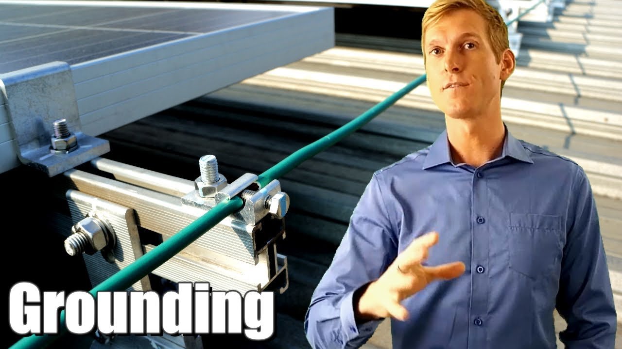
Image source: YouTube / Solar Solution (YouTube thumbnail (fair-use with source credit))
Grounding is the foundation of any EMP protection strategy, but it's also where most people get it wrong. The goal of grounding for EMP protection is not the same as the goal of grounding for electrical safety. You need to understand the difference.
For electrical code compliance, grounding provides a safe path for fault current. It prevents shock hazards and allows breakers to trip. For EMP protection, grounding provides a low-impedance path that shunts induced energy away from sensitive components before it can do damage.
The key difference is impedance at high frequencies.
Standard grounding with a single copper rod driven into the earth works well for 60 Hz AC current. But an E1 pulse contains frequencies in the megahertz range. At those frequencies, a long ground wire acts as an inductor, it resists the flow of high-frequency current.
That means the energy doesn't dissipate into the ground quickly enough. Instead, it reflects back into the equipment.
What proper EMP grounding looks like:
- Short, direct ground wires, avoid long loops or coils
- Multiple ground rods bonded together to lower overall resistance
- A ground resistance below 10 ohms (measured at DC)
- All equipment chassis bonded to the same ground plane
- Ground wire gauge no smaller than 6 AWG for the main bond
What doesn't work:
- A single ground rod at the service entrance with long wire runs to the roof
- Ground wires that are coiled or looped (they act as inductors)
- Grounding only the AC side while leaving the DC side floating
- Using ground clamps that aren't rated for outdoor use
If your solar array is mounted on a metal roof that's properly bonded to the grounding system, that roof can act as a partial shield. It won't stop a direct E1 strike, but it will reduce the induced field strength reaching the panels. This is one reason why metal-roofed buildings tend to fare better in EMP scenarios.
The science of grounding for surge events is well established. The National Electrical Code (NEC) provides specific guidelines for bonding and grounding of solar photovoltaic systems, and those guidelines form a solid baseline for EMP protection as well. For a deeper dive into the fundamentals of how solar panels generate electricity and why grounding matters at the circuit level, that's a helpful read.
Remember: grounding alone won't protect you. It's one piece of a multi-layer strategy. You need grounding plus surge protection plus physical isolation to have a truly resilient system.
The grounding layer ensures that when your surge protection devices activate, they have a clean path to dump that energy into the earth instead of into your equipment.
That's where we're heading next, surge protection. But before we go there, make sure you understand the grounding you already have. If you can't measure your ground resistance or if your ground wire runs are longer than 10 feet before hitting a rod, you have work to do.
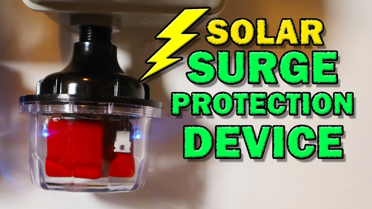
Image source: YouTube / Tools Tech And Gear (YouTube thumbnail (fair-use with source credit))
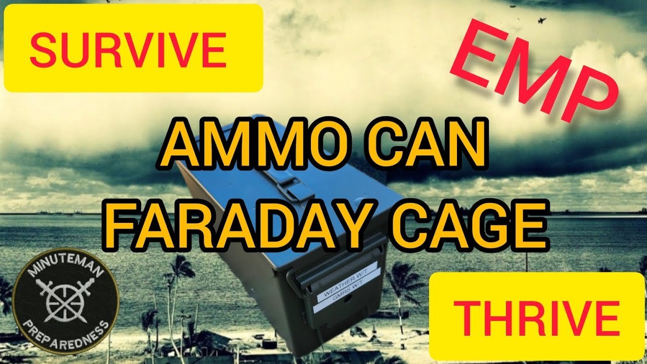
Image source: YouTube / Minuteman Preparedness (YouTube thumbnail (fair-use with source credit))

Similar Posts