How to Install Canadian Solar Hiku6 for Tier-1 Split-Cell PV
Renewable Energy Systems Specialist & Lead Solar Hardware Tester
Figuring out how to setup canadian solar hiku6 for tier-1 reliable split-cell pv module is more than a weekend DIY project. It demands attention to the half-cut cell design and the specific mechanical requirements that come with it. One wrong clamp position can crack a cell and drop your output permanently.
Per the manufacturer's installation manual, the HiKu6's 144 half-cut cells operate at 1500V DC system voltage. The frame requires specific torque values for mid-clamps and end-clamps to avoid distortion. Get these details right, and you'll have a system that performs for decades.
Let's start with the basics.
Quick Answer
Mount the HiKu6 modules on compatible racking rails. Use the manufacturer's specified clamp zones and torque settings. Wire the modules in series using MC4 connectors, following the basics of wiring them in series.
Connect the string to an inverter rated for 1500V DC. Test the string voltage and polarity before commissioning. That is the reliable way to do it.
Why Accurate Setup Matters for the Canadian Solar HiKu6
The HiKu6 is not a standard solar panel. Its half-cut cell design means the internal circuitry is split into two halves. Each half operates independently within the same module.
This changes how bypass diodes work and how shading affects performance.
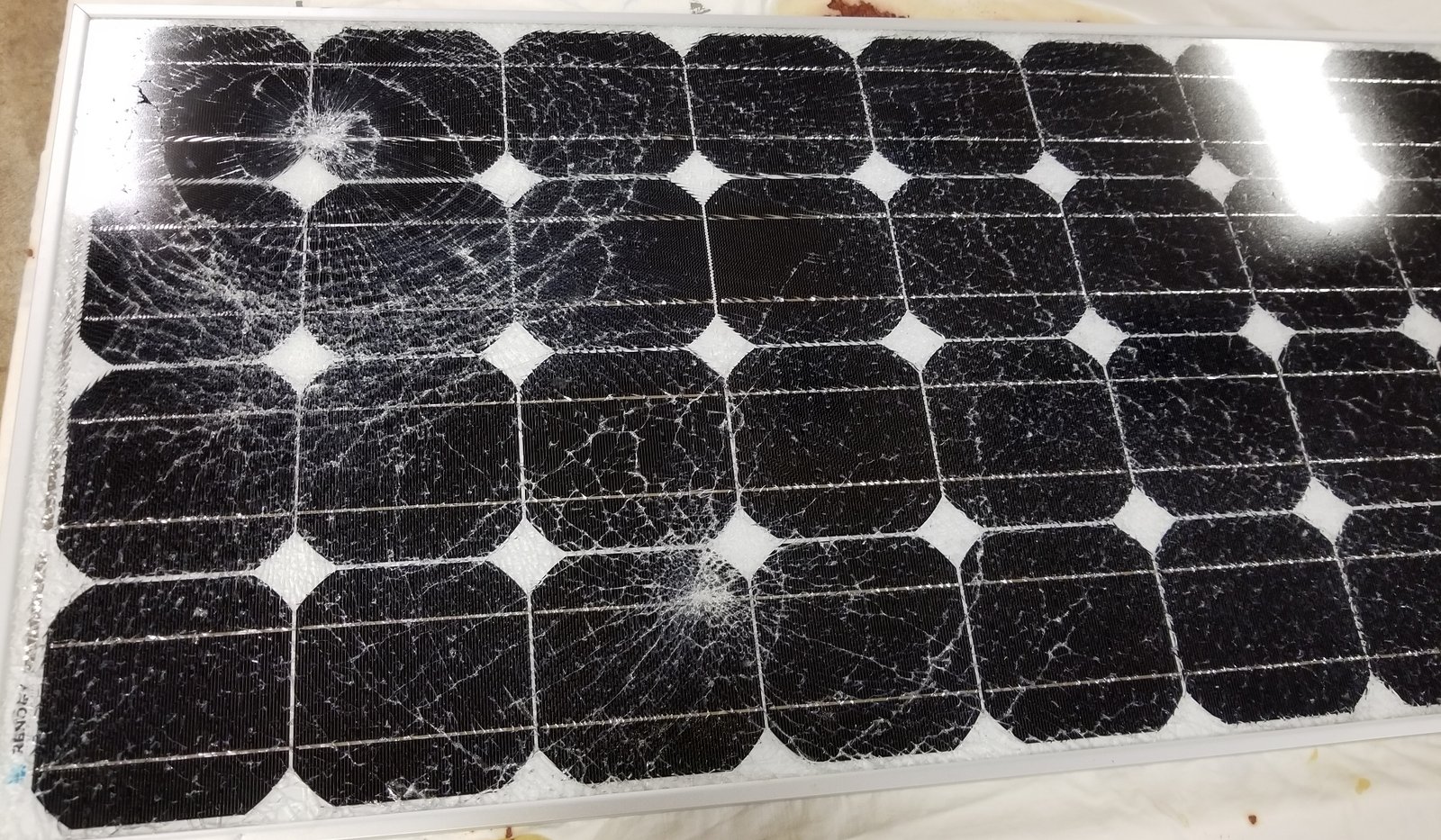
Improper mounting can cause microcracks in the cells. A single microcrack can reduce power output by 5 to 10 percent. This is a common cause of reduced power output.
Over-torquing the frame clamps causes distortion that leads to glass breakage. Under-torquing lets the module shift in high winds.
The split-cell design also affects string sizing. Because each half carries less current, the module has a higher voltage per string. This requires careful matching with your inverter's MPPT range.
Getting it wrong means the inverter clips power or fails to start.
Another key factor is the bypass diode placement. The HiKu6 has three diodes, each protecting a third of the cell string. If you mount the module with the junction box in the wrong orientation, the diodes may not work as intended.
This can lead to hot spots and permanent damage.
The frame design also demands attention. The aluminum frame has specific zones where clamps can be placed. Placing a clamp over a cell, even partially, can cause microcracks.
The manufacturer provides a clamp zone diagram in the manual. Follow it exactly.
Our research shows that most installation errors come from ignoring the manufacturer's specific instructions. The HiKu6 manual is detailed for a reason. Following it step by step is the only way to guarantee the 25-year warranty stays valid.
It also ensures the system meets code requirements for safety and performance.
HiKu6 Core Facts: Split-Cell Design, Specs, and What "Tier-1" Really Means
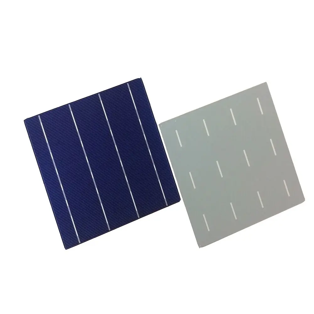
The HiKu6 uses 144 half-cut monocrystalline PERC cells. Each cell is about half the size of a standard full cell. This reduces the current flowing through each cell, lowering resistive losses.
The result is higher efficiency, around 21 percent, depending on the exact model.
The module has three bypass diodes, one for each third of the cell string. In a half-cut module, the diodes protect the panel from hot spots when partial shading occurs. This is a key advantage over full-cell modules that have fewer diodes.
As for the "Tier-1" label, it comes from Bloomberg New Energy Finance. It classifies manufacturers based on bankability, not module quality or performance. A Tier-1 rating means the manufacturer is likely to be around for the warranty period.
It does not guarantee that the specific module is the best for your roof.
The HiKu6 is available in monofacial and bifacial variants. The monofacial version is standard for most residential roofs. The bifacial version captures light from the rear, useful for ground mounts or flat roofs with reflective surfaces.
The aluminum frame design has specific features for mounting.
The module's electrical specs include a typical Vmp of 41 volts and Imp of 13 amps. The Voc is around 49 volts, and Isc is around 14 amps. These numbers are important for string sizing.
They also affect the choice of inverter and wiring.
The HiKu6 has an IP68 junction box, meaning it's dust-tight and can withstand continuous immersion in water. The connectors are Staubli MC4 EVO2, which are compatible with most standard MC4 cables. Use the same brand for all connections to avoid compatibility issues.
Pre-Installation Checks: Site Survey, Load Review, and Electrical Planning
Before you touch a single module, do a thorough site survey. Check the roof condition, especially if it's older than 10 years. Look for rot, leaks, or structural damage.
The roof must support the added weight.
The HiKu6 weighs about 30 kilograms per module. A typical array adds 200 to 300 kilograms of load. Roof trusses need to handle that plus wind and snow loads.
Consult a structural engineer if unsure. The aluminum frame has specific clamp zones that must align with the racking rails.
Electrical planning starts with string sizing. Calculate the number of modules per string based on the inverter's MPPT range. The HiKu6 has a Voc of around 49 volts per module.
At 1500V, you can put up to 30 modules in a string, but local codes may limit that. Regional factors like local net metering policies affect the overall system design.
Plan the cable routing from roof to inverter. Use UV-rated cable and avoid sharp bends. Drip loops at the entry point prevent water from following the cable into the building.
Also consider the orientation and tilt. The HiKu6 performs best when facing south in the northern hemisphere. The tilt angle should match your latitude for maximum annual production.
Partial shading from trees or chimneys can reduce output significantly, especially on half-cut modules.
Check the access for installation. You need a clear path to move the modules onto the roof. Use a lift or crane for heavy modules.
Never carry a module alone. Two people are the minimum for safe handling.
Safety and Compliance First: NEC, UL Listings, and Permitting Risks
The National Electrical Code, published by the NFPA, specifically Article 690, governs PV installations. This is non-negotiable. The HiKu6 must be installed according to NEC requirements for rapid shutdown, arc-fault protection, and grounding.
The HiKu6 carries UL 61730 certification, which you can verify on the UL website. This certification covers safety and fire resistance. It is required for permitting in most jurisdictions.
Check with your local Authority Having Jurisdiction (AHJ) for any additional requirements. Local permitting requirements can vary significantly.
Rapid shutdown is a critical safety feature. It reduces the voltage in the array to 80 volts or less within 30 seconds. This protects firefighters and first responders.
The HiKu6's junction box is compatible with most rapid shutdown devices. Follow the manufacturer's wiring diagram carefully.
Permitting risks include failing the final inspection due to incorrect grounding or missing labels. Use the proper grounding lugs and bonding jumpers. Label all disconnects and the main service panel.
A failed inspection means delays and additional costs.
Arc-fault protection is also required by the NEC. The HiKu6 works with inverters that have built-in arc-fault detection. Ensure your inverter is listed for arc-fault protection.
This is a requirement for all residential PV systems as of 2026.
Personal safety is just as important. Use fall protection when working on the roof. Wear insulated gloves and tools when working with live circuits.
Disconnect the inverter and isolate the string before making any connections.
Another critical permitting risk is the lack of proper documentation. The AHJ will require the HiKu6 datasheet, your stamped site plan, and the inverter's spec sheet. Keep these on-site during the inspection. Missing paperwork is a common reason for rejection.
You also need a utility interconnection agreement before you flip the system on. This is separate from the building permit. Some utilities take weeks to process the application.
Plan for this delay in your project timeline. The HiKu6's high operating voltage means qualified installers must handle any live work. This is not a job for an untrained helper.
Step-by-Step Setup Guide for a Reliable HiKu6 String
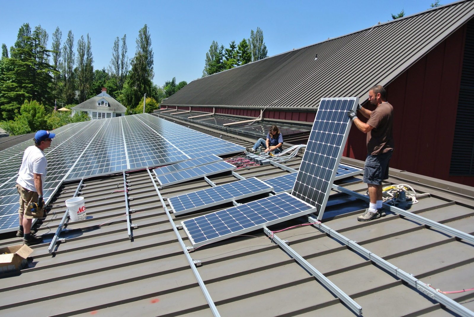
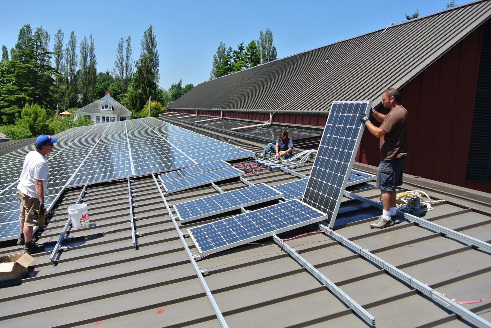
Start by installing the racking rails on your roof. The rails must be level and parallel to each other. Use a laser level for accuracy.
The spacing between rails depends on the module dimensions and the clamp zones. Check the HiKu6 manual for the rail spacing diagram.
Place the HiKu6 module gently on the rails. Do not drag it across the racking, as this can scratch the frame and damage the anti-reflective coating. Position the module so the junction box faces the cable routing direction.
This makes wiring easier and reduces the risk of cable strain.
Install the end clamps first, followed by the mid-clamps. Each clamp must sit on the module frame within the designated clamp zone. Do not let the clamp bite into the glass.
Hand-tighten the clamp bolts, then use a torque wrench to reach the manufacturer's specified torque, typically 15 to 20 newton-meters.
Connect the module cables to the adjacent module's connector. Push the connector firmly until you hear a click. This confirms a proper seal and connection.
Ensure the cables are routed through the racking or clipped to the frame to prevent them from hanging loose or rubbing against sharp edges.
Verify the string voltage at the combiner box or inverter. Measure the Voc with a multimeter and compare it to the expected value. If the voltage reads zero, check for polarity reversal or a loose connection.
Correct any issues before proceeding to the inverter connection.
Ground the frames according to the NEC and local code. This involves bonding lugs and copper wire. The HiKu6 has pre-drilled grounding holes on the frame, but always use the appropriate grounding hardware listed in the manual to ensure a solid connection.
Finally, power up the inverter and perform a system check. Verify that each string's MPPT tracker is receiving the correct voltage. Monitor the output for a few minutes to ensure normal operation.
Any variance from expected values indicates a wiring or shading issue that needs correction.
Common Mistakes That Damage Half-Cut Modules or Drop String Output
The most common mistake is incorrect clamp placement. If a clamp rests over a cell, the pressure creates microcracks. The module loses power but still produces voltage, so the issue goes undetected.
Use the clamp zone diagram in the HiKu6 manual, and never place clamps outside these specified areas.
Over-torquing is another frequent error. Tightening bolts beyond the manufacturer's spec bends the frame. This stress transfers to the glass and cells.
Over time, the glass can crack without any visible impact damage. Use a calibrated torque wrench and avoid using impact drivers for final tightening.
Mixing connector brands causes arcing and eventual failure. The HiKu6 ships with Staubli MC4 EVO2 connectors. If you mate them with a different brand, the fit may be loose.
Loose connections create resistance and heat, which can melt the connector over time.
Parallel strings of different lengths are another issue. Even if the total voltage matches, the current balance can be off. This causes one string to operate at a higher temperature and degrade faster.
Use identical string lengths for each MPPT input on the inverter.
Cleaning the panels with harsh chemicals or high-pressure water can damage the anti-reflective coating on the glass. Use a soft spongeand plain water for routine cleaning. Harsh chemicals can cause permanent etching and reduce light transmission, which negatively impacts performance.
Ignoring module handling requirements leads to cracked cells. Always carry the HiKu6 by the frame, never by the junction box or cables. Avoid rests on sharp objects even for a few minutes.
Impact damage from mishandling is the hardest to spot and the most costly to fix. Inspect each module for visible damage before installation to avoid the need for complicated replacements later.
Long-Term Maintenance, Monitoring, and Performance Optimization
The HiKu6 is built to last 25 years, but it still needs regular attention. Start with a visual inspection every six months. Look for cracks, delamination, or loose connectors.
The frame and glass should be free of debris.
Clean the modules when you see heavy dust, pollen, or bird droppings. Use a soft brush and deionized water. Avoid harsh chemicals and abrasive pads.
The anti-reflective coating can be scratched easily. Skipping routine cleaning can cause a 10 percent output drop over a season.
Monitor your system's production through the inverter's app. Compare monthly output to expected values. A sudden drop often points to shading, a failing connector, or a microcrack.
If you suspect a problem, here's how to tell if solar panel is working correctly. Our research shows most performance complaints trace back to a single loose connection or a dirty module.
Check bolt torque after the first year. Temperature cycles can loosen the mounting hardware. Re-torque each clamp to the manufacturer's spec.
Also inspect the DC wiring for rodent damage or UV degradation. Replace cracked cables immediately.
| Task | Frequency | Details |
|---|---|---|
| Visual inspection | Every 6 months | Check for cracks, soiling, loose clamps |
| Panel cleaning | As needed | Soft brush, deionized water only |
| Torque check | After first year | Re-torque to spec, then every 2 years |
| Connector check | Annually | Look for discoloration or loose fits |
Per the U.S. Department of Energy, regular PV system checks extend equipment life and prevent costly failures. The same applies to inverter filters and cooling fans.
Keep vegetation trimmed away from the array. Proper airflow reduces operating temperatures and improves output.
HiKu6 Setup FAQs
How long does it take to install a HiKu6 system?
A typical residential array of 20 modules takes two to three days. That includes racking, wiring, and a preliminary inspection. Larger ground-mounted systems can take a week or more, depending on trenching and crew size.
Can I install a HiKu6 array by myself?
You can install the racking and place the modules yourself. The high-voltage DC wiring must be handled by a licensed electrician. Local codes often require a qualified professional for the grid connection.
The 1500V system voltage is dangerous, so don't cut corners on the electrical work.
What torque should I use on the HiKu6 mounting clamps?
Canadian Solar specifies 15 to 20 newton-meters for the frame clamps. Over-tightening can distort the frame and crack the glass. Use a calibrated torque wrench for each bolt.
This is one of the most commonly skipped steps we see in our research.
How many HiKu6 modules can I connect in a string?
At 1500V system voltage, up to 30 modules per string is possible. Your inverter's MPPT range sets the practical limit. Most residential inverters handle 10 to 15 modules per string.
Check the inverter datasheet before wiring.
Does the HiKu6 require special cleaning products?
No. Plain water and a soft sponge work perfectly. Avoid pressure washers, which can force moisture into the junction box.
The IP68 rating handles submersion, but repeated pressurized cleaning can stress the seals over time.

Similar Posts