How to Wire 3 Solar Panels in Parallel (Step-by-Step)

So you have three solar panels and you want to wire them together. Maybe you are building a small off-grid system for a shed or camper. Or you already have one panel and want to add two more without replacing everything.
The question "How to Connect 3 Solar Panels in Parallel?" comes up a lot in DIY solar forums.
The short version is straightforward. Parallel wiring keeps the voltage the same and adds up the current. But the real answer involves fuses, wire sizes, and understanding your charge controller's limits.
Miss those details and you could melt a connector or start a fire. Per the National Electrical Code (NEC Article 690), any solar array with more than two parallel strings needs overcurrent protection on each string. Let us walk through it properly so your system is safe and efficient.
Quick Answer
To connect 3 solar panels in parallel, join all positive wires together and all negative wires together. Voltage stays the same. Current adds up.
Use a Y-branch connector or combiner box. Fuse each string if the combined current exceeds the panel's max series fuse rating. Check your charge controller limits.
Verify polarity before connecting.
Why Doing This Wrong Can Cost You (or Worse)
Parallel wiring looks easy. Strip three positive wires. Twist them together.
Connect to the charge controller. Done, right? Not quite.
The hidden danger is called backfeed current. When one panel gets shaded or damaged, the other two panels push their full current backward through that weaker string. That current can exceed the wire's rating or the panel's internal bypass diodes.
Here is where things get real. A standard 100W panel has a short-circuit current around 5.5 to 6.5 amps. Combine three of them and you have roughly 16.5 to 19.5 amps of potential backfeed flowing through a single string.
If that string's wiring is only rated for 10 amps, the insulation melts. DC arcs do not extinguish easily. They sustain themselves and can ignite nearby materials.
We see builders skip the fuses because it saves a few dollars. Then they wonder why their system stopped working. Aggregate user reports across DIY forums confirm that unfused parallel arrays are the most common cause of connector failure in small systems.
The fix costs less than ten bucks per string.
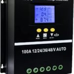
Another expensive mistake is ignoring the charge controller's input current limit. A typical 30 amp PWM controller cannot handle three 100W panels in parallel if the combined current exceeds 20 amps at the battery voltage. You either oversize the controller or use an MPPT controller that can manage the higher input and step it down.
The bottom line is this: parallel wiring is simple. The safety calculations around it are not optional. You need to know three specific numbers from your panel's label before you buy a single connector.
Parallel Wiring: What's Actually Happening Inside the Wires
Parallel wiring means you connect every positive terminal together and every negative terminal together. Think of it like three garden hoses all feeding into one bucket. Each hose delivers water at the same pressure.
The bucket fills faster because more water flows in at once.
In electrical terms, voltage stays constant. If each panel outputs 18 volts at maximum power, your combined output is still 18 volts. Current adds up.
Three panels each producing 5.5 amps give you 16.5 amps total. That is the fundamental difference from series wiring, where voltage adds up and current stays the same.
Why does this matter for your system? Most off-grid setups use a 12 volt battery bank. Panels designed for 12 volt systems have a Vmp (voltage at maximum power) around 17 to 19 volts.
That is enough to charge a 12 volt battery without needing extra voltage. Parallel wiring keeps you in that sweet spot.
There is an important detail here. The combined current flows through a single pair of wires going to the charge controller. Those wires need to be thick enough to handle the total current without dropping too much voltage.
A 3 percent voltage drop is the typical target. For a 20 amp system with a 10 foot run, you need at least 10 AWG wire. Going smaller means wasted power and heat buildup.
Another thing to understand is how the current splits when panels are mismatched. If one panel is partially shaded, its voltage drops. The other panels try to push current into it instead of toward the charge controller.
That is the backfeed scenario we mentioned earlier. Proper fusing stops that current from damaging the shaded panel or its wiring.
The key takeaway is straightforward. Parallel wiring is ideal when your battery bank is 12 volts and you want to add panels without raising voltage. But the combined current demands attention to wire sizing, fusing, and charge controller limits.
The Three Numbers You Must Know Before Buying a Single Connector
Every solar panel has a label on the back. That label contains three critical numbers you need before wiring anything in parallel. Do not trust the marketing specs.
Read the actual sticker.
Open Circuit Voltage (Voc)
This is the voltage the panel produces when no load is connected. It is higher than the operating voltage. For a typical 12 volt panel, Voc is around 21 to 23 volts.
In parallel wiring, Voc does not add up. All panels share the same voltage. But you still need to know this number because your charge controller has a maximum input voltage rating.
Even though parallel wiring keeps voltage low, some cheap PWM controllers cannot handle a Voc above 25 volts. Check the manual.
Short Circuit Current (Isc)
This is the maximum current the panel can produce when its terminals are shorted. It is usually 10 to 15 percent higher than the operating current. A 100W panel might have an Isc of 6.2 amps.
In parallel, the total possible current is the sum of all Isc values. Three panels would give you roughly 18.6 amps. That number determines your wire gauge and fuse size.
Maximum Series Fuse Rating
This is the most overlooked number on the label. It tells you the maximum current that can flow backward through the panel without damaging it. Typical values are 10 or 15 amps.
If your combined current from the other panels exceeds this rating, you must fuse each string individually. NEC 690.8 requires this protection when the sum of the parallel strings exceeds the panel's maximum series fuse rating.
Here is a quick reference table for common panel sizes:
| Panel Wattage | Typical Isc | Max Series Fuse Rating | Combined Current (3 panels) | Fuse Required? |
|---|---|---|---|---|
| 100W | 6.2A | 10A | 18.6A | Yes |
| 150W | 8.5A | 15A | 25.5A | Yes |
| 200W | 11.0A | 15A | 33.0A | Yes |
| 50W | 3.2A | 10A | 9.6A | No (if under 10A) |
You can see the pattern. Almost every common panel size needs fusing when running three in parallel. The only exception might be very small panels where the combined current stays under the maximum series fuse rating.
Step-by-Step: Connecting 3 Panels in Parallel Safely
Now we get to the actual process. Do this in the order listed. Skipping steps can damage components or create safety hazards.
Tools and Materials You Need
Gather everything before you start. Nothing worse than running inside twice because you forgot the wire strippers.
- Three solar panels with matching voltage (within 5 percent)
- MC4 Y-branch connectors (one pair for positive, one for negative)
- In-line MC4 fuse holders with appropriate fuses
- 10 AWG or 8 AWG solar cable (check your total distance)
- Wire strippers and crimping tool for MC4 connectors
- Multimeter with DC current and voltage capability
- Combiner box (optional but recommended for three or more strings)
Step 1: Verify Panel Compatibility
Check that all three panels have similar voltage. Measure the Voc of each panel with the multimeter in sunlight. They should be within 5 percent of each other.
If one panel reads 21 volts and another reads 19 volts, the lower voltage panel will drag down the entire array. You lose performance and risk backfeed issues.
Step 2: Measure and Cut Your Cables
Measure the distance from each panel to the combiner point. Add a little slack for movement. Cut your positive and negative cables to length.
Strip about 3/8 inch of insulation from each end.
Step 3: Install Fuses on Each Positive String
Crimp an in-line fuse holder onto the positive wire of each panel. Install a fuse rated at 1.56 times the panel's Isc. That multiplier comes from NEC 690.8.
It accounts for continuous operation and safety margin. For a 6.2 amp Isc, use a 10 amp fuse. For an 8.5 amp Isc, use a 15 amp fuse.
The fuse goes on the positive wire before any connection point.
Step 4: Connect the Y-Branch or Combiner Box
If using Y-branch connectors, plug each panel's positive wire into the positive branch. Then plug all negatives into the negative branch. The single output goes to your charge controller.
If using a combiner box, land each positive wire on a fused terminal and each negative wire on a common bus bar. Combiner boxes are cleaner and safer for permanent installations.
Step 5: Verify Polarity Before Connecting to the Controller
This step prevents the most expensive mistake. Measure the voltage at the combiner output. The reading should match the Voc of a single panel, not zero or a low number.
If you see zero, you reversed polarity somewhere. Check each connection. A reverse polarity connection can destroy a charge controller in milliseconds.
Step 6: Connect to the Charge Controller
Turn the charge controller off or disconnect the battery first. Connect the positive and negative wires from the combiner to the solar input terminals on the controller. Then reconnect the battery.
Finally, turn the controller on. Check the display to confirm it sees voltage from the panels.
Step 7: Test the System
Measure the current flowing from the array with your clamp meter. It should be close to the sum of each panel's Isc if they are in full sun. A significantly lower reading means one panel is underperforming or has a bad connection.
Fuse Each String (Yes, All Three)
We already touched on this, but it deserves its own section. Fusing is not optional. It is the difference between a system that runs for years and one that fails in a month.
Why Backfeed Is Dangerous
Imagine one of your three panels develops an internal short. The other two panels see that short as a low resistance path. They dump their full current into the failed panel.
That current can be 10 or 20 amps flowing through wires and diodes rated for half that amount. The wires heat up. The insulation softens.
Eventually, a short circuit develops where the wire touches something grounded. Now you have a fire.
How to Calculate the Right Fuse Size
NEC 690.8 specifies a multiplier of 1.56 for solar circuit overcurrent protection. Here is the math for a typical panel:
- Panel Isc: 6.2 amps
- Multiply by 1.56: 6.2 x 1.56 = 9.67 amps
- Round up to the next standard fuse size: 10 amps
The same calculation for a 150W panel with 8.5 amp Isc gives you 13.26 amps. Round up to 15 amps. Never round down.
A fuse that trips under normal conditions is useless.
Where to Place the Fuses
Each fuse goes on the positive wire of each panel, as close to the panel as practical. In a Y-branch setup, that means an in-line MC4 fuse holder between the panel and the branch connector. In a combiner box, the box itself has fuse holders for each string.
Do not put a single fuse on the combined output. That protects the wire to the charge controller, but it does not protect individual panels from backfeed. Each string needs its own fuse.
When You Might Not Need a Fuse
There is one scenario where fusing is unnecessary. If the combined short circuit current from all parallel strings is less than the panel's maximum series fuse rating, you can skip the fuses. For example, two 50W panels with an Isc of 3.2 amps each give a combined 6.4 amps.
If the panel's max series fuse rating is 10 amps, the backfeed cannot exceed the rating. But with three panels, the combined 9.6 amps approaches the limit. Most installers fuse anyway for safety margin.

Similar Posts